Cisco 1601 Hardware Installation Guide - Page 50
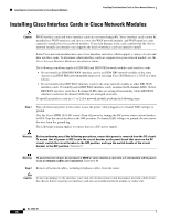
Installing Cisco Interface Cards in Cisco Network Modules
 |
View all Cisco 1601 manuals
Add to My Manuals
Save this manual to your list of manuals |
Page 50 highlights
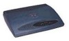
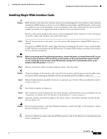
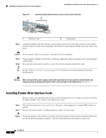
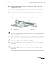
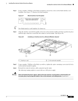
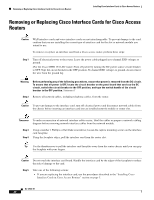
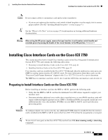
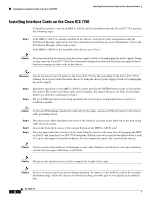
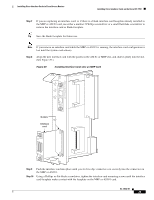
Installing Cisco Interface Cards in Cisco Network Modules Installing Cisco Interface Cards in Cisco Access Routers Installing Cisco Interface Cards in Cisco Network Modules Caution WAN interface cards and voice interface cards are not interchangeable. Voice interface cards cannot be installed in a WAN interface card slot or a two-slot WAN network module, and WAN interface cards cannot be installed in voice network modules. To prevent damage to the card, confirm that the slot or network module you intend to use supports the kind of interface card you intend to install. Some Cisco network modules have one or two interface card slots, which support a variety of voice and data interface cards. To determine which interface cards are supported in your network module, see the Cisco Network Modules Hardware Installation Guide. The following conditions apply to ISDN BRI and ISDN PRI network modules and interface cards: • Do not install an ISDN BRI WAN interface card or an ISDN BRI network module in the same chassis as an ISDN PRI network module unless you are using Cisco IOS Release 11.3(3)T or a later release. • Do not install newer BRI WAN interface cards in the same network module as older BRI WAN interface cards. To identify newer BRI WAN interface cards, examine the B-channel LEDs. Newer BRI WAN interface cards have B-channel LEDs that are arranged horizontally. Older BRI WAN interface cards have B-channel LEDs that are arranged vertically. To install an interface card in a 1- or 2-slot network module, perform the following steps: Step 1 Turn off electrical power to the router. Leave the power cable plugged in to channel ESD voltages to ground. (For the Cisco MWR 1941-DC router) Turn off power by turning the DC power source circuit breaker to OFF. Tape the circuit breaker in the OFF position. To channel ESD voltages to ground, do not remove the wire from the ground lug. The following warning applies to routers that use a DC power supply: Warning Before performing any of the following procedures, ensure that power is removed from the DC circuit. To ensure that all power is OFF, locate the circuit breaker on the panel board that services the DC circuit, switch the circuit breaker to the OFF position, and tape the switch handle of the circuit breaker in the OFF position. Statement 7 Warning To avoid electric shock, do not insert a WAN or voice interface card into a 2-slot module while power is on or network cables are connected. Statement 68 Step 2 Remove all network cables, including telephone cables, from the router. Caution To prevent damage to the interface card, turn off electrical power and disconnect network cables from the chassis before inserting an interface card into an installed network module or router slot. OL-12842-01 18
-
 1
1 -
2
-
3
-
4
-
5
-
6
-
7
-
8
-
9
-
10
-
11
-
12
-
13
-
14
-
15
-
16
-
17
-
18
-
19
-
20
-
21
-
22
-
23
-
24
-
25
-
26
-
27
-
28
-
29
-
30
-
31
-
32
-
33
-
34
-
35
-
36
-
37
-
38
-
39
-
40
-
41
-
42
-
43
-
44
-
 45
45 -
 46
46 -
 47
47 -
 48
48 -
 49
49 -
 50
50 -
 51
51 -
 52
52 -
 53
53 -
 54
54 -
 55
55 -
56
-
57
-
58
-
59
-
60
-
61
-
62
-
63
-
64
-
65
-
66
-
67
-
68
-
69
-
70
-
71
-
72
-
73
-
74
-
75
-
76
-
77
-
78
-
79
-
80
-
81
-
82
-
83
-
84
-
85
-
86
-
87
-
88
-
89
-
90
-
91
-
92
-
93
-
94
-
95
-
96
-
97
-
98
-
99
-
100
-
101
-
102
-
103
-
104
-
105
-
106
-
107
-
108
-
109
-
110
-
111
-
112
-
113
-
114
-
115
-
116
-
117
-
118
-
119
-
120
-
121
-
122
-
123
-
124
-
125
-
126
-
127
-
128
-
129
-
130
-
131
-
132
-
133
-
134
-
135
-
136
-
137
-
138
-
139
-
140
-
141
-
142
-
143
-
144
-
145
-
146
-
147
-
148
-
149
-
150
-
151
-
152
-
153
-
154
-
155
-
156
-
157
-
158
-
159
-
160
-
161
-
162
-
163
-
164
-
165
-
166
-
167
-
168
-
169
-
170
-
171
-
172
-
173
-
174
-
175
-
176
-
177
-
178
-
179
-
180
-
181
-
182
-
183
-
184
-
185
-
186
-
187
-
188
-
189
-
190
-
191
-
192
-
193
-
194
-
195
-
196
-
197
-
198
-
199
-
200
-
201
-
202
-
203
-
204
-
205
-
206
-
207
-
208
-
209
-
210
-
211
-
212
-
213
-
214
-
215
-
216
 |
 |