Cisco 1601 Hardware Installation Guide - Page 51
Blank Interface Card Faceplate, Installing an Interface Card in a Network Module Typical
 |
View all Cisco 1601 manuals
Add to My Manuals
Save this manual to your list of manuals |
Page 51 highlights
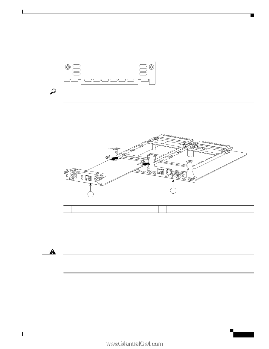
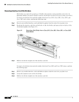
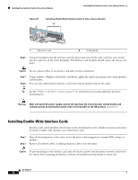
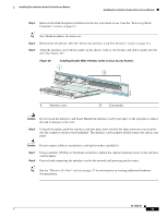
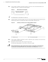
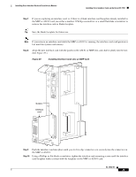
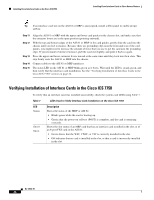
Installing Cisco Interface Cards in Cisco Access Routers Installing Cisco Interface Cards in Cisco Network Modules Step 3 Using a number 1 Phillips or flat-blade screwdriver, loosen the screws on the blank interface card faceplate. (See Figure 27.) Remove the blank faceplate. Figure 27 Blank Interface Card Faceplate DO NOT INSTALL WAN INTERFACE CARDS WITH POWER APPLIED H6649 Tip Save blank interface card faceplates for future use. Step 4 Align the interface card with the guides in the slot on the network module and slide it gently into place until the edge connector is seated into the connector on the module. (See Figure 28.) Figure 28 Installing an Interface Card in a Network Module (Typical) 2E 2W W1 H7219 B1 B2 BRI S/T 1 ETH 1 ACT LNK ACT LNK WO ETHERNET 0 AUI EN 2 1 Interface card 2 2-slot network module Step 5 Step 6 Using a number 1 Phillips or flat-blade screwdriver, tighten the captive mounting screws into the holes on the network module faceplate. Reinstall the network interface cables and power up the router. The following warning applies to routers that use a DC power supply: Warning After wiring the DC power supply, remove the tape from the circuit breaker switch handle and reinstate power by moving the handle of the circuit breaker to the ON position. Statement 8 OL-12842-01 19
-
 1
1 -
2
-
3
-
4
-
5
-
6
-
7
-
8
-
9
-
10
-
11
-
12
-
13
-
14
-
15
-
16
-
17
-
18
-
19
-
20
-
21
-
22
-
23
-
24
-
25
-
26
-
27
-
28
-
29
-
30
-
31
-
32
-
33
-
34
-
35
-
36
-
37
-
38
-
39
-
40
-
41
-
42
-
43
-
44
-
45
-
 46
46 -
 47
47 -
 48
48 -
 49
49 -
 50
50 -
 51
51 -
 52
52 -
 53
53 -
 54
54 -
 55
55 -
 56
56 -
57
-
58
-
59
-
60
-
61
-
62
-
63
-
64
-
65
-
66
-
67
-
68
-
69
-
70
-
71
-
72
-
73
-
74
-
75
-
76
-
77
-
78
-
79
-
80
-
81
-
82
-
83
-
84
-
85
-
86
-
87
-
88
-
89
-
90
-
91
-
92
-
93
-
94
-
95
-
96
-
97
-
98
-
99
-
100
-
101
-
102
-
103
-
104
-
105
-
106
-
107
-
108
-
109
-
110
-
111
-
112
-
113
-
114
-
115
-
116
-
117
-
118
-
119
-
120
-
121
-
122
-
123
-
124
-
125
-
126
-
127
-
128
-
129
-
130
-
131
-
132
-
133
-
134
-
135
-
136
-
137
-
138
-
139
-
140
-
141
-
142
-
143
-
144
-
145
-
146
-
147
-
148
-
149
-
150
-
151
-
152
-
153
-
154
-
155
-
156
-
157
-
158
-
159
-
160
-
161
-
162
-
163
-
164
-
165
-
166
-
167
-
168
-
169
-
170
-
171
-
172
-
173
-
174
-
175
-
176
-
177
-
178
-
179
-
180
-
181
-
182
-
183
-
184
-
185
-
186
-
187
-
188
-
189
-
190
-
191
-
192
-
193
-
194
-
195
-
196
-
197
-
198
-
199
-
200
-
201
-
202
-
203
-
204
-
205
-
206
-
207
-
208
-
209
-
210
-
211
-
212
-
213
-
214
-
215
-
216
 |
 |