Cisco 1601 Hardware Installation Guide - Page 39
Installing Blank Faceplates, Double-wide to Single-wide Slot Conversion
 |
View all Cisco 1601 manuals
Add to My Manuals
Save this manual to your list of manuals |
Page 39 highlights
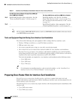
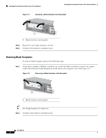
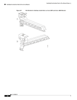
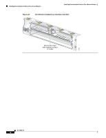
Installing Cisco Interface Cards in Cisco Access Routers Installing Cisco Interface Cards in Cisco Access Routers Tip For an introduction to Cisco interface card form factors, see the "Introduction to Cisco Interface Cards" section in Cisco Interface Cards for Cisco Access Routers. To prepare an interface card slot for interface card installation, perform the tasks listed in Table 6. Table 6 Preparing Interface Card Slots for Installation Step 1 Step 2 Step 3 Double-wide to Single-wide Slot Conversion Single-wide to Double-wide Slot Conversion Remove the blank faceplates from the slots you plan to use. Remove blank faceplates from the slots you plan to (See the "Removing Blank Faceplates" section on page 8.) use. (See the "Removing Blank Faceplates" section on page 8.) Insert the slot divider. (See the "Installing Interface Card Slot Remove the slot divider. (See the "Installing Interface Dividers" section on page 9.) Card Slot Dividers" section on page 9.) Install the interface card. (See the "Installing Single-Wide Install the interface card. (See the "Installing Interface Cards" section on page 15.) Double-Wide Interface Cards" section on page 16.) Installing Blank Faceplates All empty chassis slots for network modules, extension modules, or interface cards must be covered with blank faceplates to ensure proper cooling and to prevent electromagnetic interference. Note Blank interface module faceplates are for single-wide interface card slots only. To install a blank faceplate over an interface card slot set up for a double-wide interface card, you must prepare the slot as for single-wide interface cards. See Table 6 for information on preparing interface card slots for different interface card form factors. To install a blank faceplate, perform the following steps: Step 1 Step 2 (For interface card slots that contained double-wide interface cards) Install a slot divider in the center of the slot to create two single-wide interface card slots. Align the captive screws with the threaded holes on the chassis. Using either a number 1 Phillips screwdriver or a small flat-blade screwdriver, tighten the captive screws until the blank faceplate is flush with the chassis. (See Figure 17.) OL-12842-01 7
-
 1
1 -
2
-
3
-
4
-
5
-
6
-
7
-
8
-
9
-
10
-
11
-
12
-
13
-
14
-
15
-
16
-
17
-
18
-
19
-
20
-
21
-
22
-
23
-
24
-
25
-
26
-
27
-
28
-
29
-
30
-
31
-
32
-
33
-
 34
34 -
 35
35 -
 36
36 -
 37
37 -
 38
38 -
 39
39 -
 40
40 -
 41
41 -
 42
42 -
 43
43 -
 44
44 -
45
-
46
-
47
-
48
-
49
-
50
-
51
-
52
-
53
-
54
-
55
-
56
-
57
-
58
-
59
-
60
-
61
-
62
-
63
-
64
-
65
-
66
-
67
-
68
-
69
-
70
-
71
-
72
-
73
-
74
-
75
-
76
-
77
-
78
-
79
-
80
-
81
-
82
-
83
-
84
-
85
-
86
-
87
-
88
-
89
-
90
-
91
-
92
-
93
-
94
-
95
-
96
-
97
-
98
-
99
-
100
-
101
-
102
-
103
-
104
-
105
-
106
-
107
-
108
-
109
-
110
-
111
-
112
-
113
-
114
-
115
-
116
-
117
-
118
-
119
-
120
-
121
-
122
-
123
-
124
-
125
-
126
-
127
-
128
-
129
-
130
-
131
-
132
-
133
-
134
-
135
-
136
-
137
-
138
-
139
-
140
-
141
-
142
-
143
-
144
-
145
-
146
-
147
-
148
-
149
-
150
-
151
-
152
-
153
-
154
-
155
-
156
-
157
-
158
-
159
-
160
-
161
-
162
-
163
-
164
-
165
-
166
-
167
-
168
-
169
-
170
-
171
-
172
-
173
-
174
-
175
-
176
-
177
-
178
-
179
-
180
-
181
-
182
-
183
-
184
-
185
-
186
-
187
-
188
-
189
-
190
-
191
-
192
-
193
-
194
-
195
-
196
-
197
-
198
-
199
-
200
-
201
-
202
-
203
-
204
-
205
-
206
-
207
-
208
-
209
-
210
-
211
-
212
-
213
-
214
-
215
-
216
 |
 |