Cisco 1601 Hardware Installation Guide - Page 143
Related Documentation, Step 2
 |
View all Cisco 1601 manuals
Add to My Manuals
Save this manual to your list of manuals |
Page 143 highlights
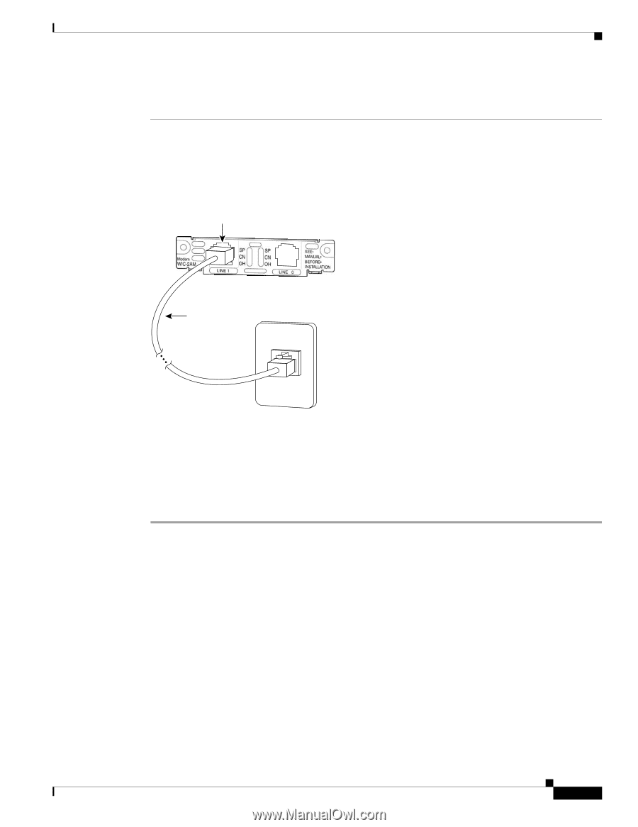
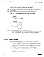
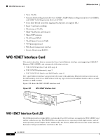
Analog Modem WAN Interface Cards Related Documentation intra-building interfaces only (Type 2 or Type 4 ports as described in GR-1089-CORE, Issue 4) and require isolation from the exposed OSP cabling. The addition of Primary Protectors is not sufficient protection in order to connect these interfaces metallically to OSP wiring. Step 2 Step 3 Connect one end of a straight-through RJ-11-to-RJ-11 cable to the pink RJ-11 port labeled LINE on the analog modem WIC. Connect the other end of the cable to a wall telephone outlet, as shown in Figure 106. Figure 106 Connecting an Analog Modem WIC to a Wall Telephone Outlet Analog modem port (RJ-11) Straight-through RJ-11 cable 37391 RJ-11 jack Step 4 Step 5 Depending on whether you have a 1-port or 2-port analog modem WIC: • For 1-port analog modem WICs, you can connect an analog telephone to the RJ-11 port labeled PHONE. This allows the dialout line to be shared between the telephone and the modem. • For 2-port analog modem WICs repeat Step 2 and Step 3 to connect the second port to a network. Turn on power to the router. Related Documentation Related documentation is available on Cisco.com. For more information, see the "Obtaining Documentation, Obtaining Support, and Security Guidelines" section on page 6. • 1- and 2-Port V.90 Modem WICs for Cisco 2600 and Cisco 3600 Series Multiservice Platforms, Cisco IOS Release 12.2(8)T feature module • AT Command Set and Register Summary for V.90 WIC-1AM and WIC-2AM Analog Modem WAN Interface Cards • Analog Modem Interface Card Configuration Notes for Cisco 1700 Series Routers • Cisco Network Modules and Interface Cards Regulatory Compliance and Safety Information • Cisco WIC-1AM-V2 and WIC-2AM-V2 Analog Modem WAN Interface Card • Modem-Router Connection Guide, tech note OL-12848-01 5
-
 1
1 -
2
-
3
-
4
-
5
-
6
-
7
-
8
-
9
-
10
-
11
-
12
-
13
-
14
-
15
-
16
-
17
-
18
-
19
-
20
-
21
-
22
-
23
-
24
-
25
-
26
-
27
-
28
-
29
-
30
-
31
-
32
-
33
-
34
-
35
-
36
-
37
-
38
-
39
-
40
-
41
-
42
-
43
-
44
-
45
-
46
-
47
-
48
-
49
-
50
-
51
-
52
-
53
-
54
-
55
-
56
-
57
-
58
-
59
-
60
-
61
-
62
-
63
-
64
-
65
-
66
-
67
-
68
-
69
-
70
-
71
-
72
-
73
-
74
-
75
-
76
-
77
-
78
-
79
-
80
-
81
-
82
-
83
-
84
-
85
-
86
-
87
-
88
-
89
-
90
-
91
-
92
-
93
-
94
-
95
-
96
-
97
-
98
-
99
-
100
-
101
-
102
-
103
-
104
-
105
-
106
-
107
-
108
-
109
-
110
-
111
-
112
-
113
-
114
-
115
-
116
-
117
-
118
-
119
-
120
-
121
-
122
-
123
-
124
-
125
-
126
-
127
-
128
-
129
-
130
-
131
-
132
-
133
-
134
-
135
-
136
-
137
-
 138
138 -
 139
139 -
 140
140 -
 141
141 -
 142
142 -
 143
143 -
 144
144 -
 145
145 -
 146
146 -
 147
147 -
 148
148 -
149
-
150
-
151
-
152
-
153
-
154
-
155
-
156
-
157
-
158
-
159
-
160
-
161
-
162
-
163
-
164
-
165
-
166
-
167
-
168
-
169
-
170
-
171
-
172
-
173
-
174
-
175
-
176
-
177
-
178
-
179
-
180
-
181
-
182
-
183
-
184
-
185
-
186
-
187
-
188
-
189
-
190
-
191
-
192
-
193
-
194
-
195
-
196
-
197
-
198
-
199
-
200
-
201
-
202
-
203
-
204
-
205
-
206
-
207
-
208
-
209
-
210
-
211
-
212
-
213
-
214
-
215
-
216
 |
 |