Cisco 1601 Hardware Installation Guide - Page 133
Multiflex Trunk Interface Card LEDs, Connecting a Multiflex Trunk Interface Card, Description, Color
 |
View all Cisco 1601 manuals
Add to My Manuals
Save this manual to your list of manuals |
Page 133 highlights
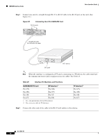
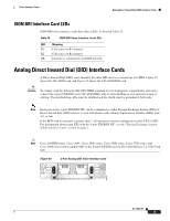
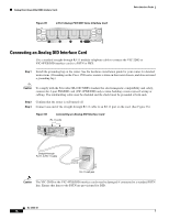
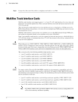
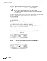
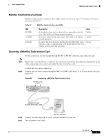
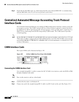
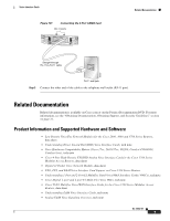
Voice Interface Cards Multiflex Trunk Interface Cards Multiflex Trunk Interface Card LEDs Multiflex trunk interface cards have three LEDs, which are shown in Figure 97 and Figure 98 and are described in Table 27. Table 27 Multiflex Trunk Interface Card LEDs LED LP LED AL LED CD LED Description A loopback or line state is detected or is manually set by the user. This LED is off during normal operation. A local or remote alarm state exists. This LED is off during normal operation. A carrier has been detected, and the internal DSU/CSU in the interface card is communicating with another DSU/CSU. This LED is on during normal operation. Color Yellow Yellow Green Connecting a Multiflex Trunk Interface Card For this connection, use the straight-through RJ-48C-to-RJ-48C cable that came with your card. Note Refer to the Cisco Modular Access Router Specifications for network-end connectors and pinouts of the cables connecting voice cards. Look under the type of interface card. Step 5 Confirm that the router is turned off. Connect one end of the straight-through RJ-48C-to-RJ-48C cable to the T1 or E1 port on the card. (See Figure 99.) Figure 99 Connecting a Multiflex Trunk Interface Card RJ-48C ports AL SEE VWIC 2MFT-E1-D1 LP MANUAL CD BEFORE CTRLR E1 1 CTRLR E1 0 INSTALLATION Straight-through RJ-48C-to-RJ-48C cable 41202 Step 6 Step 7 RJ-48C wall jack Connect the other end to the T1 or E1 wall jack (RJ-48C) at your site. Turn on power to the router. OL-12847-01 17
-
 1
1 -
2
-
3
-
4
-
5
-
6
-
7
-
8
-
9
-
10
-
11
-
12
-
13
-
14
-
15
-
16
-
17
-
18
-
19
-
20
-
21
-
22
-
23
-
24
-
25
-
26
-
27
-
28
-
29
-
30
-
31
-
32
-
33
-
34
-
35
-
36
-
37
-
38
-
39
-
40
-
41
-
42
-
43
-
44
-
45
-
46
-
47
-
48
-
49
-
50
-
51
-
52
-
53
-
54
-
55
-
56
-
57
-
58
-
59
-
60
-
61
-
62
-
63
-
64
-
65
-
66
-
67
-
68
-
69
-
70
-
71
-
72
-
73
-
74
-
75
-
76
-
77
-
78
-
79
-
80
-
81
-
82
-
83
-
84
-
85
-
86
-
87
-
88
-
89
-
90
-
91
-
92
-
93
-
94
-
95
-
96
-
97
-
98
-
99
-
100
-
101
-
102
-
103
-
104
-
105
-
106
-
107
-
108
-
109
-
110
-
111
-
112
-
113
-
114
-
115
-
116
-
117
-
118
-
119
-
120
-
121
-
122
-
123
-
124
-
125
-
126
-
127
-
 128
128 -
 129
129 -
 130
130 -
 131
131 -
 132
132 -
 133
133 -
 134
134 -
 135
135 -
 136
136 -
 137
137 -
 138
138 -
139
-
140
-
141
-
142
-
143
-
144
-
145
-
146
-
147
-
148
-
149
-
150
-
151
-
152
-
153
-
154
-
155
-
156
-
157
-
158
-
159
-
160
-
161
-
162
-
163
-
164
-
165
-
166
-
167
-
168
-
169
-
170
-
171
-
172
-
173
-
174
-
175
-
176
-
177
-
178
-
179
-
180
-
181
-
182
-
183
-
184
-
185
-
186
-
187
-
188
-
189
-
190
-
191
-
192
-
193
-
194
-
195
-
196
-
197
-
198
-
199
-
200
-
201
-
202
-
203
-
204
-
205
-
206
-
207
-
208
-
209
-
210
-
211
-
212
-
213
-
214
-
215
-
216
 |
 |