Cisco 1601 Hardware Installation Guide - Page 198
Connecting Radio Antennas to the Access Point HWIC
 |
View all Cisco 1601 manuals
Add to My Manuals
Save this manual to your list of manuals |
Page 198 highlights
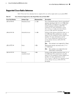
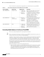
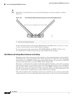
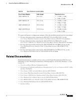
Access Point High-Speed WAN Interface Cards Access Point High-Speed WAN Interface Cards Table 41 lists the Cisco antennas that are supported for use on the dual-mode access point HWIC. Table 41 Cisco Antennas Supported on the Dual-Mode Access Point HWIC Cisco Part Number AIR-ANTM2050D-R Antenna Type Omnidirectional AIR-ANTM4050V-R Diversity omnidirectional AIR-ANTM5560P-R Patch Maximum Gain • 2.2 dBi in the 2.4-GHz band • 5 dBi in the 5-GHz band • 4 dBi in the 2.4-GHz band • 5 dBi in the 5-GHz band • 5.5 dBi in the 2.4-GHz band • 6 dBi in the 5-GHz band Description This is the default antenna. Swivel-mount dipole antenna operating in the 2.4- to 2.5-GHz band. This antenna is designed for use with Cisco wireless products utilizing an RP-TNC connector. For more information, see the Cisco Multiband Swivel-Mount Dipole Antenna (AIR-ANTM2050D-R) document. Ceiling-mount antenna operating in the 2.4to 2.5-GHz band. This antenna has a clip that allows it to be mounted to a drop-ceiling cross member. For more information, see the Cisco Multiband Diversity Omnidirectional Ceiling-Mount Antenna (AIR-ANTM4050V-R) document. Wall-mount antenna operating in the 2.4- to 2.5-GHz band. For more information, see the Cisco Multiband Wall-Mount Antenna (AIR-ANTM5560P-R) document. Connecting Radio Antennas to the Access Point HWIC This section contains information about connecting the radio antennas. Note Before connecting the radio antennas, install the access point HWIC in the router. See Installing Cisco Interface Cards in Cisco Access Routers for more information. In addition to antenna orientation, wireless access point installation location with respect to all wireless clients plays a significant role in determining overall network performance. Clients at the furthest coverage points might have 10% to 50% of the bandwidth of clients close to it. Wireless network coverage in one area or location might need to be lowered to improve the performance of other clients. Because antennas transmit and receive radio signals, their performance can be adversely affected by the surrounding environment including distance between access point and client, physical obstructions, or radio frequency (RF) interference. Follow these guidelines to ensure the best possible performance: • Wherever possible, mount the access point HWIC and antenna where the wireless devices would be within sight and avoid physical obstructions. Barriers along the line of sight between client and access point will degrade the wireless radio signals. access point HWICs and antennas can be installed above floor level in office environments or near the ceiling for better performance since most obstructions tend to be near floor level. OL-12854-01 6
-
 1
1 -
2
-
3
-
4
-
5
-
6
-
7
-
8
-
9
-
10
-
11
-
12
-
13
-
14
-
15
-
16
-
17
-
18
-
19
-
20
-
21
-
22
-
23
-
24
-
25
-
26
-
27
-
28
-
29
-
30
-
31
-
32
-
33
-
34
-
35
-
36
-
37
-
38
-
39
-
40
-
41
-
42
-
43
-
44
-
45
-
46
-
47
-
48
-
49
-
50
-
51
-
52
-
53
-
54
-
55
-
56
-
57
-
58
-
59
-
60
-
61
-
62
-
63
-
64
-
65
-
66
-
67
-
68
-
69
-
70
-
71
-
72
-
73
-
74
-
75
-
76
-
77
-
78
-
79
-
80
-
81
-
82
-
83
-
84
-
85
-
86
-
87
-
88
-
89
-
90
-
91
-
92
-
93
-
94
-
95
-
96
-
97
-
98
-
99
-
100
-
101
-
102
-
103
-
104
-
105
-
106
-
107
-
108
-
109
-
110
-
111
-
112
-
113
-
114
-
115
-
116
-
117
-
118
-
119
-
120
-
121
-
122
-
123
-
124
-
125
-
126
-
127
-
128
-
129
-
130
-
131
-
132
-
133
-
134
-
135
-
136
-
137
-
138
-
139
-
140
-
141
-
142
-
143
-
144
-
145
-
146
-
147
-
148
-
149
-
150
-
151
-
152
-
153
-
154
-
155
-
156
-
157
-
158
-
159
-
160
-
161
-
162
-
163
-
164
-
165
-
166
-
167
-
168
-
169
-
170
-
171
-
172
-
173
-
174
-
175
-
176
-
177
-
178
-
179
-
180
-
181
-
182
-
183
-
184
-
185
-
186
-
187
-
188
-
189
-
190
-
191
-
192
-
 193
193 -
 194
194 -
 195
195 -
 196
196 -
 197
197 -
 198
198 -
 199
199 -
 200
200 -
 201
201 -
 202
202 -
 203
203 -
204
-
205
-
206
-
207
-
208
-
209
-
210
-
211
-
212
-
213
-
214
-
215
-
216
 |
 |