Cisco 1601 Hardware Installation Guide - Page 48
Installing Double-Wide Interface Cards
 |
View all Cisco 1601 manuals
Add to My Manuals
Save this manual to your list of manuals |
Page 48 highlights
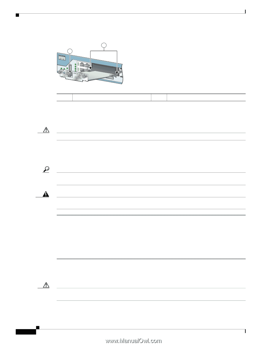
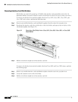
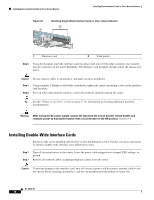
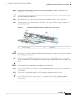
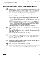
Installing Cisco Interface Cards in Cisco Access Routers Installing Cisco Interface Cards in Cisco Access Routers Figure 25 1 Installing Single-Wide Interface Cards in Cisco Access Routers 2 121080 1 Interface card 2 Card guides Step 6 Using the faceplate, push the interface card into place until you feel the edge connector seat securely into the connector on the router backplane. The interface card faceplate should contact the chassis rear panel. Caution Do not connect cables to an interface card until you have installed it. Step 7 Step 8 Using a number 1 Phillips or flat-blade screwdriver, tighten the captive mounting screws on the interface card faceplate. Proceed with connecting the interface card to the network and powering up the router. Tip See the "Where to Go Next" section on page 27 for information on locating additional hardware documentation. Warning After wiring the DC power supply, remove the tape from the circuit breaker switch handle and reinstate power by moving the handle of the circuit breaker to the ON position. Statement 8 Installing Double-Wide Interface Cards Interface cards can be installed either before or after mounting the router, whichever is most convenient. To install a double-wide interface card, follow these steps: Step 1 Step 2 Turn off electrical power to the router. Leave the power cable plugged in to channel ESD voltages to ground. Remove all network cables, including telephone cables, from the router. Caution To prevent damage to the interface card, turn off electrical power and disconnect network cables from the chassis before inserting an interface card into an installed network module or router slot. OL-12842-01 16
-
 1
1 -
2
-
3
-
4
-
5
-
6
-
7
-
8
-
9
-
10
-
11
-
12
-
13
-
14
-
15
-
16
-
17
-
18
-
19
-
20
-
21
-
22
-
23
-
24
-
25
-
26
-
27
-
28
-
29
-
30
-
31
-
32
-
33
-
34
-
35
-
36
-
37
-
38
-
39
-
40
-
41
-
42
-
 43
43 -
 44
44 -
 45
45 -
 46
46 -
 47
47 -
 48
48 -
 49
49 -
 50
50 -
 51
51 -
 52
52 -
 53
53 -
54
-
55
-
56
-
57
-
58
-
59
-
60
-
61
-
62
-
63
-
64
-
65
-
66
-
67
-
68
-
69
-
70
-
71
-
72
-
73
-
74
-
75
-
76
-
77
-
78
-
79
-
80
-
81
-
82
-
83
-
84
-
85
-
86
-
87
-
88
-
89
-
90
-
91
-
92
-
93
-
94
-
95
-
96
-
97
-
98
-
99
-
100
-
101
-
102
-
103
-
104
-
105
-
106
-
107
-
108
-
109
-
110
-
111
-
112
-
113
-
114
-
115
-
116
-
117
-
118
-
119
-
120
-
121
-
122
-
123
-
124
-
125
-
126
-
127
-
128
-
129
-
130
-
131
-
132
-
133
-
134
-
135
-
136
-
137
-
138
-
139
-
140
-
141
-
142
-
143
-
144
-
145
-
146
-
147
-
148
-
149
-
150
-
151
-
152
-
153
-
154
-
155
-
156
-
157
-
158
-
159
-
160
-
161
-
162
-
163
-
164
-
165
-
166
-
167
-
168
-
169
-
170
-
171
-
172
-
173
-
174
-
175
-
176
-
177
-
178
-
179
-
180
-
181
-
182
-
183
-
184
-
185
-
186
-
187
-
188
-
189
-
190
-
191
-
192
-
193
-
194
-
195
-
196
-
197
-
198
-
199
-
200
-
201
-
202
-
203
-
204
-
205
-
206
-
207
-
208
-
209
-
210
-
211
-
212
-
213
-
214
-
215
-
216
 |
 |