HP Cluster Platform Express v2010 Workgroup System and Cluster Platform Expres - Page 15
Zero-U Mounted Power Distribution Unit for c7000 Configurations
 |
View all HP Cluster Platform Express v2010 manuals
Add to My Manuals
Save this manual to your list of manuals |
Page 15 highlights
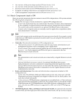
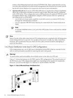
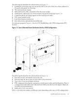
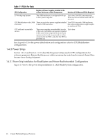
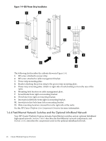
The following list describes the callouts shown in Figure 1-1: 1. Installation screws and cage nuts secure the PDU to the side of the rack column, adjacent to the rack's side panels for servicing. 2. The rack's front left column. 3. Main inlet power cable, connected to the site power supply. 4. Outlet power cables (up to 4) which connect to the power strips (see Figure 1-3). 5. Connector shield, providing support for the outlet power cables. 6. PDU main breaker switch. 7. Individual breaker switches (4). 8. Direction of view, towards the rear of the rack. For reference purposes, Figure 1-2 shows a CPE BladeSystem with c7000 configuration PDU location. Figure 1-2 Zero-U Mounted Power Distribution Unit for c7000 Configurations 3 4 2 5 1 The following list describes the callouts shown in Figure 1-2: 1. Direction of view, towards the rear of the rack. 2. Place the PDU 1U down from the top of the c-Class enclosure. 3. Top of the c-Class server blade enclosure. 4. PDU component showing the main power switch, power cable, and four breakers. There is a similar unit on the other side of the enclosure that is not shown in this figure. (There are two PDUs for each enclosure.) 5. Right side of rack, rear column. Table 1-1 provides the number of PDUs per rack, depending on the type of CPE configuration: 1.4 CPE Architecture Overview 15
-
 1
1 -
2
-
3
-
4
-
5
-
6
-
7
-
8
-
9
-
 10
10 -
 11
11 -
 12
12 -
 13
13 -
 14
14 -
 15
15 -
 16
16 -
 17
17 -
 18
18 -
 19
19 -
 20
20 -
21
-
22
-
23
-
24
-
25
-
26
-
27
-
28
-
29
-
30
-
31
-
32
-
33
-
34
-
35
-
36
-
37
-
38
-
39
-
40
-
41
-
42
-
43
-
44
-
45
-
46
-
47
-
48
-
49
-
50
-
51
-
52
-
53
-
54
-
55
-
56
-
57
-
58
-
59
-
60
-
61
-
62
-
63
-
64
-
65
-
66
-
67
-
68
-
69
-
70
-
71
-
72
-
73
-
74
-
75
-
76
-
77
-
78
-
79
-
80
-
81
-
82
-
83
-
84
-
85
-
86
-
87
-
88
-
89
-
90
-
91
-
92
-
93
-
94
-
95
-
96
-
97
-
98
-
99
-
100
-
101
-
102
-
103
-
104
-
105
-
106
-
107
-
108
-
109
-
110
-
111
-
112
-
113
-
114
-
115
-
116
-
117
-
118
-
119
-
120
-
121
-
122
-
123
-
124
-
125
-
126
-
127
-
128
-
129
-
130
 |
 |
