HP Cluster Platform Express v2010 Workgroup System and Cluster Platform Expres - Page 25
Identifying Node Port and PCI Slot Assignments, Table 1-3 Rack-Mountable Server Control Nodes
 |
View all HP Cluster Platform Express v2010 manuals
Add to My Manuals
Save this manual to your list of manuals |
Page 25 highlights
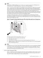
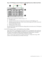
Table 1-3 Rack-Mountable Server Control Nodes HP ProLiant DLxxx Gx with Opteron Processors DL145 Gx DL165 Gx DL385 Gx HP ProLiant DLxxx Gx with Xeon Processors DL140 Gx DL160 Gx DL380 Gx Note: Rack-mountable control nodes are referred to as external control nodes and are considered an option for BladeSystem configurations. If the external control node option is not selected, one of the server blades in a c3000 or c7000 enclosure must be designated as a control node. 1.4.5.1 Identifying Node Port and PCI Slot Assignments The HP Cluster Platform Servers and Workstations Overview lists and describes the node slot and port assignments for every model of server used in HP Cluster Platform configurations. Knowing the port and PCI slot identification and assignments, you can complete the point-to-point cabling for every component in the cluster by using the cabling tables provided in the appendices. In a preconfigured cluster, the cables are labeled with the origin and destination of every cable connector. Generally, you need only make a few connections to configure a cluster at your site. CPE configurations require only that you complete the local LAN and power connections before you can proceed with powering up the cluster and setting up the operating environment. Figure 1-11 shows an example of a ProLiant DL380 server configured as a control node to show you a general overview of the typical node connections. See the HP Cluster Platform Servers and Workstations Overview for the specific server models employed as control and compute nodes in your cluster, and the slot and port assignments for your server models. It will also identify which TCP/IP ports are available for local LAN connections in each model server. Figure 1-11 Typical System Connections for a Control Node (Example Only) 3 2 1 2 3 4 5 6 7 The following list describes the callouts in Figure 1-11: 1. PCI slot 1, where the 64-bit 133 MHz host channel adapter (HCA) might be installed. This card provides the node end of the link to the InfiniBand system interconnect, if the cluster contains an ISR 9024 interconnect. 2. A VGA (video) port that is optionally connected to the TFT7600 KVM, possibly through the optional 8-port console switch. 3. Embedded network interface card Integrated Lights Out (iLO) RJ-45 port. This is a server management port, connected by a CAT5e cable to the ProCurve console network switch. This connection enables server hardware management for operations such as boot and shut down. 4. A USB port that is optionally connected to the TFT7600 KVM, possibly through the optional 8-port console switch. 1.4 CPE Architecture Overview 25
-
 1
1 -
2
-
3
-
4
-
5
-
6
-
7
-
8
-
9
-
10
-
11
-
12
-
13
-
14
-
15
-
16
-
17
-
18
-
19
-
 20
20 -
 21
21 -
 22
22 -
 23
23 -
 24
24 -
 25
25 -
 26
26 -
 27
27 -
 28
28 -
 29
29 -
 30
30 -
31
-
32
-
33
-
34
-
35
-
36
-
37
-
38
-
39
-
40
-
41
-
42
-
43
-
44
-
45
-
46
-
47
-
48
-
49
-
50
-
51
-
52
-
53
-
54
-
55
-
56
-
57
-
58
-
59
-
60
-
61
-
62
-
63
-
64
-
65
-
66
-
67
-
68
-
69
-
70
-
71
-
72
-
73
-
74
-
75
-
76
-
77
-
78
-
79
-
80
-
81
-
82
-
83
-
84
-
85
-
86
-
87
-
88
-
89
-
90
-
91
-
92
-
93
-
94
-
95
-
96
-
97
-
98
-
99
-
100
-
101
-
102
-
103
-
104
-
105
-
106
-
107
-
108
-
109
-
110
-
111
-
112
-
113
-
114
-
115
-
116
-
117
-
118
-
119
-
120
-
121
-
122
-
123
-
124
-
125
-
126
-
127
-
128
-
129
-
130
 |
 |
