HP Cluster Platform Express v2010 Workgroup System and Cluster Platform Expres - Page 26
Connecting to an External Network
 |
View all HP Cluster Platform Express v2010 manuals
Add to My Manuals
Save this manual to your list of manuals |
Page 26 highlights
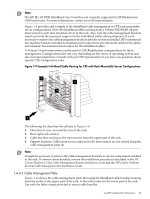
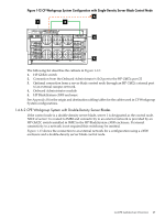
5. Embedded network interface card NIC 2, RJ-45 port which is optionally connected by a CAT5e cable to the local network (LAN). 6. Embedded network interface, connected by a CAT5e cable to the HP ProCurve administrative network switch. This connection enables cluster management tasks such as job submission and monitoring. 7. Optional redundant power supplies. 1.4.6 Connecting to an External Network An optional connection to an external 10/100/1000Base-T network is supported from the control node using NIC2. Connecting to an external network depends on the type of CPE configuration, as follows: • CP Workgroup System with single-density server blades (see Section 1.4.6.1) • CP Workgroup System with double-density server blades (see Section 1.4.6.2) • CPE BladeSystem configurations with an external rack-mountable server control node (see Section 1.4.6.3) • CPE BladeSystem configurations with double-density server blades and an external rack-mountable server control node (see Section 1.4.6.4) • CPE BladeSystem configurations with a single-density server blade control node (see Section 1.4.6.5) • CPE BladeSystem configurations with a double-density server blade control node (see Section 1.4.6.6) • CPE with rack-mountable servers only (see Section 1.4.6.7) Title: The following sections show the combined Administrative, Console, and Gigabit Ethernet network connections in addition to the options for connecting CPE clusters to an external network. 1.4.6.1 CPE Workgroup System with Single-Density Server Blades If the control node is a single-density server blade and the configuration uses an HP BladeSystem c3000 enclosure, both NIC1 and NIC2 of the server blade are routed to IMB1. A connection to an external network can be made to one of the external ports on the HP GbE2c switch installed in IMB1. The intention is for traffic to the external network to be routed through NIC2 on the control node blade. Since both of the server blade connections to the Administrative network and the control node's connection to the external network are through the same switch, the cluster must be configured with a suitable addressing scheme to separate the administrative port addresses (NIC1) from the external network addresses. Additional separation may be achieved by configuring a VLAN with switch ports 1-8 as members (see Section 2.6 for more information). Caution: Set up the VLAN carefully and in accordance with the procedures described in Section 2.6 to ensure that access to the switch management functions is available over the required network. Figure 1-12 shows the connection to an external network for a configuration using a c3000 enclosure and a single-density server blade control node. 26 Cluster Platform Express Overview
-
 1
1 -
2
-
3
-
4
-
5
-
6
-
7
-
8
-
9
-
10
-
11
-
12
-
13
-
14
-
15
-
16
-
17
-
18
-
19
-
20
-
 21
21 -
 22
22 -
 23
23 -
 24
24 -
 25
25 -
 26
26 -
 27
27 -
 28
28 -
 29
29 -
 30
30 -
 31
31 -
32
-
33
-
34
-
35
-
36
-
37
-
38
-
39
-
40
-
41
-
42
-
43
-
44
-
45
-
46
-
47
-
48
-
49
-
50
-
51
-
52
-
53
-
54
-
55
-
56
-
57
-
58
-
59
-
60
-
61
-
62
-
63
-
64
-
65
-
66
-
67
-
68
-
69
-
70
-
71
-
72
-
73
-
74
-
75
-
76
-
77
-
78
-
79
-
80
-
81
-
82
-
83
-
84
-
85
-
86
-
87
-
88
-
89
-
90
-
91
-
92
-
93
-
94
-
95
-
96
-
97
-
98
-
99
-
100
-
101
-
102
-
103
-
104
-
105
-
106
-
107
-
108
-
109
-
110
-
111
-
112
-
113
-
114
-
115
-
116
-
117
-
118
-
119
-
120
-
121
-
122
-
123
-
124
-
125
-
126
-
127
-
128
-
129
-
130
 |
 |
