HP Cluster Platform Express v2010 Workgroup System and Cluster Platform Expres - Page 16
Power Strips
 |
View all HP Cluster Platform Express v2010 manuals
Add to My Manuals
Save this manual to your list of manuals |
Page 16 highlights
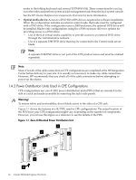
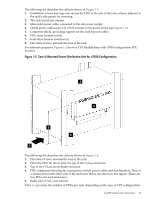
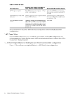
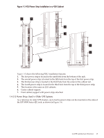
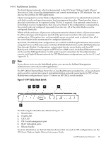
Table 1-1 PDUs Per Rack CPE Configuration Number of Power Supplies Installed in the c-Class Enclosure or Rack Components Number of 0U Mounted PDUs Required CP Workgroup System The c3000 enclosure is configured with up Up to two 24A PDUs are necessary to four power supplies. when an external control node and TFT are used CPE BladeSystem with c7000 There are up to five power supplies installed Two PDUs for each c7000 enclosure, enclosure in each c7000 enclosure. but some configurations might require an additional PDU. CPE with rack-mountable servers The power supplies are embedded in each Up to four of the rack-mountable components installed in the rack. Some components do not have a power switch and are powered-on when connected to the PDU, and after the PDU is powered-on. See Appendix E for the power distribution and configuration rules for CPE BladeSystem configurations. 1.4.3 Power Strips Section 1.4.3.1 and Section 1.4.3.2 describe the power strips used in CPE configurations for reference purposes. Ensure that the power cables are properly seated and reconnect them if they became loose during shipment. 1.4.3.1 Power Strip Installation for BladeSystem and Newer Rack-Mountable Configurations Figure 1-3 shows the power strip installation in a 42U BladeSystem configuration. 16 Cluster Platform Express Overview
-
 1
1 -
2
-
3
-
4
-
5
-
6
-
7
-
8
-
9
-
10
-
 11
11 -
 12
12 -
 13
13 -
 14
14 -
 15
15 -
 16
16 -
 17
17 -
 18
18 -
 19
19 -
 20
20 -
 21
21 -
22
-
23
-
24
-
25
-
26
-
27
-
28
-
29
-
30
-
31
-
32
-
33
-
34
-
35
-
36
-
37
-
38
-
39
-
40
-
41
-
42
-
43
-
44
-
45
-
46
-
47
-
48
-
49
-
50
-
51
-
52
-
53
-
54
-
55
-
56
-
57
-
58
-
59
-
60
-
61
-
62
-
63
-
64
-
65
-
66
-
67
-
68
-
69
-
70
-
71
-
72
-
73
-
74
-
75
-
76
-
77
-
78
-
79
-
80
-
81
-
82
-
83
-
84
-
85
-
86
-
87
-
88
-
89
-
90
-
91
-
92
-
93
-
94
-
95
-
96
-
97
-
98
-
99
-
100
-
101
-
102
-
103
-
104
-
105
-
106
-
107
-
108
-
109
-
110
-
111
-
112
-
113
-
114
-
115
-
116
-
117
-
118
-
119
-
120
-
121
-
122
-
123
-
124
-
125
-
126
-
127
-
128
-
129
-
130
 |
 |
