HP Cluster Platform Express v2010 Workgroup System and Cluster Platform Expres - Page 19
Fast-Ethernet Switches, HP Cluster Platform Gigabit Ethernet, Interconnect Guide
 |
View all HP Cluster Platform Express v2010 manuals
Add to My Manuals
Save this manual to your list of manuals |
Page 19 highlights
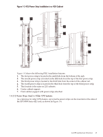
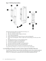
1.4.4.1 Fast-Ethernet Switches The Fast-Ethernet network, which is documented in the HP Cluster Platform Gigabit Ethernet Interconnect Guide, is used for administrative and console networking in CPE solutions. You can also use the switches for MPI applications. Cluster management on server blade configurations is supported over an administration network with both console and operating-system level management branches. These branches share a physical switch that can be separated using VLANs, if required. If an optional control node is not included in your configuration, then one server blade in the configuration is designated as the control node and configured separately from the rest. All of the other blades must be configured identically. Within a blade enclosure, all processor subsystems must be identical; that is, all processors must be of the same type and frequency, and all of the processors must have the same memory configuration. If the option for a rack-mountable server as control node is selected, then all of the server blades in the system must be configured identically. By default, CPE BladeSystem configurations are available with the Gigabit Ethernet interconnect using the ProCurve 2824 interconnect with the HP GbE2c Blade Switch and the HP Blade Ethernet Pass-through Module. Configurations using double-density server blades and three HP BladeSystem c7000 enclosures require an HP ProCurve 2848 switch. An In-Band Ethernet network can be used for MPI applications. For the point-to-point connections for the administrative, console, and Gigabit Ethernet network for CPE BladeSystem configurations, see Section B.2, and Appendix D. Note: If you choose not to use the InfiniBand option, you can use the In-Band Management (administrative network) for MPI applications. The HP GbE2c Ethernet Blade Switch for c-Class BladeSystem is installed in a c-Class enclosure and is used for system interconnect and administration network requirements in CPE c-Class BladeSystem configurations. Figure 1-5 shows an HP GbE2c switch module. Figure 1-5 HP GbE2c Blade Switch 1 23 4 5 6 The following list describes the callouts in Figure 1-5: 1. Reset button 2. Health LED 3. UID LED 4. DB-9 serial management port 5. RJ-45 1Gb uplink ports 6. Release handle For more information on the Fast-Ethernet devices that are used in CPE configurations, see the HP Cluster Platform Gigabit Ethernet Interconnect Guide. 1.4 CPE Architecture Overview 19
-
 1
1 -
2
-
3
-
4
-
5
-
6
-
7
-
8
-
9
-
10
-
11
-
12
-
13
-
 14
14 -
 15
15 -
 16
16 -
 17
17 -
 18
18 -
 19
19 -
 20
20 -
 21
21 -
 22
22 -
 23
23 -
 24
24 -
25
-
26
-
27
-
28
-
29
-
30
-
31
-
32
-
33
-
34
-
35
-
36
-
37
-
38
-
39
-
40
-
41
-
42
-
43
-
44
-
45
-
46
-
47
-
48
-
49
-
50
-
51
-
52
-
53
-
54
-
55
-
56
-
57
-
58
-
59
-
60
-
61
-
62
-
63
-
64
-
65
-
66
-
67
-
68
-
69
-
70
-
71
-
72
-
73
-
74
-
75
-
76
-
77
-
78
-
79
-
80
-
81
-
82
-
83
-
84
-
85
-
86
-
87
-
88
-
89
-
90
-
91
-
92
-
93
-
94
-
95
-
96
-
97
-
98
-
99
-
100
-
101
-
102
-
103
-
104
-
105
-
106
-
107
-
108
-
109
-
110
-
111
-
112
-
113
-
114
-
115
-
116
-
117
-
118
-
119
-
120
-
121
-
122
-
123
-
124
-
125
-
126
-
127
-
128
-
129
-
130
 |
 |
