HP Cluster Platform Express v2010 Workgroup System and Cluster Platform Expres - Page 24
Cabling Guidelines
 |
View all HP Cluster Platform Express v2010 manuals
Add to My Manuals
Save this manual to your list of manuals |
Page 24 highlights
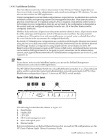
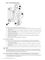
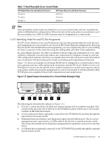
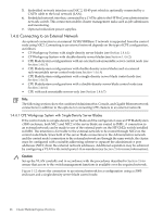
Figure 1-10 Cable Management Plate 1 2 3 4 5 The following list describes the callouts in Figure 1-10: 1. Fabric cable management strap with a metal ring and a hook-and-loop closure to secure the cable bundles. 2. Single screw attaching the strap to the plate, enabling you to change to a longer length strap for larger cable bundles. 3. The strap passes through the cut-out slots in the cable management plate to provide full support for a cable bundle. 4. Secure the strap by passing it through the metal ring on the strap and pressing on the hook-and-loop closure. 5. The direction of view, towards the rear of the rack. 1.4.4.4 Cabling Guidelines If you need to install or replace cables in your CPE configuration, follow these guidelines: • Never pull on the cable; pull only on the head shell, keeping the head shell horizontal as you disconnect the cable. • Always strap and support the cables as you proceed, so that no cable strain is exerted on the connector. • Read Chapter 7 in the HP Cluster Platform InfiniBand Interconnect Installation and User's Guide. Note: You can make the connections while all the devices in the cluster are powered up and booted. This method enables you to verify each connection as you make the connection, by observing the link status LEDsin the devices each end of the cable. 1.4.5 Control Nodes for BladeSystem or Rack-Mountable Server Configurations The following table lists the servers that are available as external control nodes for HP BladeSystem or rack-mountable server configurations: 24 Cluster Platform Express Overview
-
 1
1 -
2
-
3
-
4
-
5
-
6
-
7
-
8
-
9
-
10
-
11
-
12
-
13
-
14
-
15
-
16
-
17
-
18
-
 19
19 -
 20
20 -
 21
21 -
 22
22 -
 23
23 -
 24
24 -
 25
25 -
 26
26 -
 27
27 -
 28
28 -
 29
29 -
30
-
31
-
32
-
33
-
34
-
35
-
36
-
37
-
38
-
39
-
40
-
41
-
42
-
43
-
44
-
45
-
46
-
47
-
48
-
49
-
50
-
51
-
52
-
53
-
54
-
55
-
56
-
57
-
58
-
59
-
60
-
61
-
62
-
63
-
64
-
65
-
66
-
67
-
68
-
69
-
70
-
71
-
72
-
73
-
74
-
75
-
76
-
77
-
78
-
79
-
80
-
81
-
82
-
83
-
84
-
85
-
86
-
87
-
88
-
89
-
90
-
91
-
92
-
93
-
94
-
95
-
96
-
97
-
98
-
99
-
100
-
101
-
102
-
103
-
104
-
105
-
106
-
107
-
108
-
109
-
110
-
111
-
112
-
113
-
114
-
115
-
116
-
117
-
118
-
119
-
120
-
121
-
122
-
123
-
124
-
125
-
126
-
127
-
128
-
129
-
130
 |
 |
