HP Cluster Platform Express v2010 Workgroup System and Cluster Platform Expres - Page 34
CPE with Rack-Mountable Servers, 1.4.7 Cable Management Components
 |
View all HP Cluster Platform Express v2010 manuals
Add to My Manuals
Save this manual to your list of manuals |
Page 34 highlights
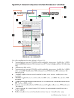
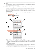
5. HP GbE2c switch installed in IMB1 of the second HP BladeSystem c7000 enclosure 6. HP GbE2c switch installed in IMB1 of the first HP BladeSystem c7000 enclosure 7. HP GbE2c switch installed in IMB3 of the first HP BladeSystem c7000 enclosure (omit if an external network connection is not necessary) 8. Four connections from an HP GbE2c switch installed in IMB2 of the second HP BladeSystem c7000 enclosure to an HP ProCurve 2824 switch (see the following note) 9. Connection from the Onboard Administrator's (OA) external link to an administrative switch (HP ProCurve 2824 switch) 10. Optional connection from the first c7000 enclosure's OA uplink to the second c7000 enclosure's OA downlink 11. HP GbE2c switch installed in IMB2 of the second HP BladeSystem c7000 enclosure 12. Connection from the OA's external link port to an administrative switch (HP ProCurve 2824 switch) 13. HP GbE2c switch installed in IMB2 of the first HP BladeSystem c7000 enclosure 14. Optional connection to an external network (such as a campus network) Note: Only one connection from each HP GbE2c switch to the HP ProCurve 2824 switch is required if the optional InfiniBand network is present. 1.4.6.7 CPE with Rack-Mountable Servers To connect to an external network from a rack-mountable server control node, connect a CAT5e cable to the NIC2 port of the designated control node to the external network (such as a campus network). 1.4.7 Cable Management Components Depending on the interconnect type, and the models of servers installed, the CPE cluster contains different types of brackets and straps for cable management. If it is necessary to remove a cable management bracket to service a unit, reverse the installation instructions found in one of the following bracket installation guides: • HP Cluster Platform c-Class Blade Cable Management Bracket Installation Guide • HP Cluster Platform 24-Node Cable Management Bracket Installation Guide • HP Cluster Platform Tab-Mount Cable Management Bracket Installation Guide • HP Cluster Platform 435761-B21 Cable Management Bracket Installation Guide Go to http://www.docs.hp.com/en/highperfcomp.html, and click on the link to the Hardware Kits -- Installation Procedures section to locate the appropriate installation document. Note: Cable management brackets are designed to support the interconnect cables during shipment. HP recommends leaving the cable management brackets installed to help prevent cables from being damaged, to provide proper strain relief, to maintain a four-inch minimum bend radius for InfiniBand cables, and to help maintain good connections. 1.5 Component Documentation Sources Depending on the CPE configuration you ordered, Table 1-4 describes the components in a CPE configuration, and defines the primary information source in the HP Cluster Platform hardware documentation. Also refer to the specific component documentation, such as the HP QuickSpecs, HP Service and Maintenance Guide, and the HP Installation Guide for each component. Two sets of 34 Cluster Platform Express Overview
-
 1
1 -
2
-
3
-
4
-
5
-
6
-
7
-
8
-
9
-
10
-
11
-
12
-
13
-
14
-
15
-
16
-
17
-
18
-
19
-
20
-
21
-
22
-
23
-
24
-
25
-
26
-
27
-
28
-
 29
29 -
 30
30 -
 31
31 -
 32
32 -
 33
33 -
 34
34 -
 35
35 -
 36
36 -
 37
37 -
 38
38 -
 39
39 -
40
-
41
-
42
-
43
-
44
-
45
-
46
-
47
-
48
-
49
-
50
-
51
-
52
-
53
-
54
-
55
-
56
-
57
-
58
-
59
-
60
-
61
-
62
-
63
-
64
-
65
-
66
-
67
-
68
-
69
-
70
-
71
-
72
-
73
-
74
-
75
-
76
-
77
-
78
-
79
-
80
-
81
-
82
-
83
-
84
-
85
-
86
-
87
-
88
-
89
-
90
-
91
-
92
-
93
-
94
-
95
-
96
-
97
-
98
-
99
-
100
-
101
-
102
-
103
-
104
-
105
-
106
-
107
-
108
-
109
-
110
-
111
-
112
-
113
-
114
-
115
-
116
-
117
-
118
-
119
-
120
-
121
-
122
-
123
-
124
-
125
-
126
-
127
-
128
-
129
-
130
 |
 |
