HP Cluster Platform Express v2010 Workgroup System and Cluster Platform Expres - Page 32
CPE BladeSystem c7000 Configurations with a Single-Density Server Blade Control
 |
View all HP Cluster Platform Express v2010 manuals
Add to My Manuals
Save this manual to your list of manuals |
Page 32 highlights
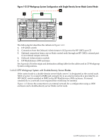
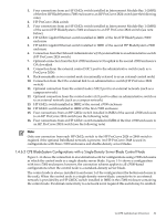
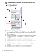
Figure 1-16 CPE BladeSystem (c7000) Configurations with a Single-Density Server Blade Control Node 2 6 3 4 6 1 5 6 8 7 9 10 The following list describes the callouts in Figure 1-16: 1. Four connections from an HP GbE2c switch installed in Interconnect Module Bay 1 (IMB1) of the first HP BladeSystem c7000 enclosure to an HP ProCurve 2824 switch (see the following note) 2. HP ProCurve 2824 switch 3. Four connections from an HP GbE2c switch installed in Interconnect Module Bay 1 (IMB1) of the second HP BladeSystem c7000 enclosure to an HP ProCurve 2824 switch (see the following note) 4. HP GbE2c switch installed in IMB1 of the second HP BladeSystem c7000 enclosure 5. HP GbE2c switch installed in IMB1 of the first HP BladeSystem c7000 enclosure 6. Connection from the Onboard Administrator's (OA) external link to an administrative switch (HP ProCurve 2824 switch) 7. Optional connection from the first c7000 enclosure's OA uplink to the second c7000 enclosure's OA downlink 8. Connection from the OA's external link (iLO2 port) to an administrative switch (HP ProCurve 2824 switch) 9. HP GbE2c switch installed in IMB2 of the first HP BladeSystem c7000 enclosure 10. Optional connection to an external network (for example, a campus network) 32 Cluster Platform Express Overview
-
 1
1 -
2
-
3
-
4
-
5
-
6
-
7
-
8
-
9
-
10
-
11
-
12
-
13
-
14
-
15
-
16
-
17
-
18
-
19
-
20
-
21
-
22
-
23
-
24
-
25
-
26
-
 27
27 -
 28
28 -
 29
29 -
 30
30 -
 31
31 -
 32
32 -
 33
33 -
 34
34 -
 35
35 -
 36
36 -
 37
37 -
38
-
39
-
40
-
41
-
42
-
43
-
44
-
45
-
46
-
47
-
48
-
49
-
50
-
51
-
52
-
53
-
54
-
55
-
56
-
57
-
58
-
59
-
60
-
61
-
62
-
63
-
64
-
65
-
66
-
67
-
68
-
69
-
70
-
71
-
72
-
73
-
74
-
75
-
76
-
77
-
78
-
79
-
80
-
81
-
82
-
83
-
84
-
85
-
86
-
87
-
88
-
89
-
90
-
91
-
92
-
93
-
94
-
95
-
96
-
97
-
98
-
99
-
100
-
101
-
102
-
103
-
104
-
105
-
106
-
107
-
108
-
109
-
110
-
111
-
112
-
113
-
114
-
115
-
116
-
117
-
118
-
119
-
120
-
121
-
122
-
123
-
124
-
125
-
126
-
127
-
128
-
129
-
130
 |
 |
