HP Cluster Platform Express v2010 Workgroup System and Cluster Platform Expres - Page 45
Server Blade Configuration Example with Three Enclosures in a 42U Rack,
 |
View all HP Cluster Platform Express v2010 manuals
Add to My Manuals
Save this manual to your list of manuals |
Page 45 highlights
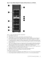
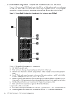
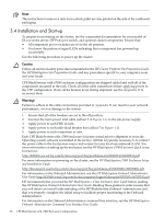
Figure 3-1 Server Blade Configuration Example with Three Enclosures in a 42U Rack 1 2 3 4 5 6 3 3 8 7 Figure 3-1 shows the following cluster components: 1. HP 10000 Series 42U rack. 2. Filler panels to close up any unused space on the front of the rack. 3. An HP c7000 enclosure with 16 half-height blades (BL460c or BL465c servers). There are three c7000 enclosures in this configuration with a total of 48 half-height server blades. 4. A control node (this is optional in some configurations). In this example, the control node is a 2U DL38x Opteron or Xeon server. (There is also the option to choose a 1U DL14x Opteron or Xeon server.) 5. HP ProCurve 2824 switch (shown facing forward in this example for illustration purposes only). All server blades (nodes) are connected to the network through the pass-through module installed in interconnect module bay 2 (IMB2) of the c7000 enclosure. 6. One TFT7600 rack-mount keyboard and monitor. This unit combines a full 17-inch WXGA+ monitor and keyboard with touch pad in a 1U format. 7. InfiniBand switch (shown facing forward for illustration purposes only). 8. Filler panel to close up reserved space on the front of the rack. Components not shown include: • 0U side-mounted power distribution units (PDUs) (see Section 1.4.2 for more information) • Power strips and their installation locations (see Section 1.4.3.1 for more information) 3.1 CPE c7000 Configuration Examples 45
-
 1
1 -
2
-
3
-
4
-
5
-
6
-
7
-
8
-
9
-
10
-
11
-
12
-
13
-
14
-
15
-
16
-
17
-
18
-
19
-
20
-
21
-
22
-
23
-
24
-
25
-
26
-
27
-
28
-
29
-
30
-
31
-
32
-
33
-
34
-
35
-
36
-
37
-
38
-
39
-
 40
40 -
 41
41 -
 42
42 -
 43
43 -
 44
44 -
 45
45 -
 46
46 -
 47
47 -
 48
48 -
 49
49 -
 50
50 -
51
-
52
-
53
-
54
-
55
-
56
-
57
-
58
-
59
-
60
-
61
-
62
-
63
-
64
-
65
-
66
-
67
-
68
-
69
-
70
-
71
-
72
-
73
-
74
-
75
-
76
-
77
-
78
-
79
-
80
-
81
-
82
-
83
-
84
-
85
-
86
-
87
-
88
-
89
-
90
-
91
-
92
-
93
-
94
-
95
-
96
-
97
-
98
-
99
-
100
-
101
-
102
-
103
-
104
-
105
-
106
-
107
-
108
-
109
-
110
-
111
-
112
-
113
-
114
-
115
-
116
-
117
-
118
-
119
-
120
-
121
-
122
-
123
-
124
-
125
-
126
-
127
-
128
-
129
-
130
 |
 |
