HP Cluster Platform Express v2010 Workgroup System and Cluster Platform Expres - Page 58
Site Preparation, 4.4 Unpacking and Removing From a Shock Pallet, 4.5 Installation and Start-up
 |
View all HP Cluster Platform Express v2010 manuals
Add to My Manuals
Save this manual to your list of manuals |
Page 58 highlights
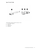
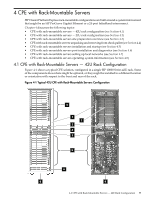
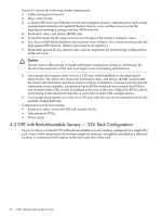
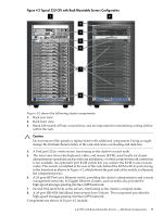
• PDUs, and power strips • Keyboard, video, mouse (KVM) and console switch 4.3 Site Preparation Site preparation tasks are generally performed before delivery of your HP CPE system. For information to prepare your site for a CPE with rack-mountable servers, see the HP Cluster Platform Site Preparation Guide: http://www.docs.hp.com/en/A-CPSPG-1D/A-CPSPG-1D.pdf 4.4 Unpacking and Removing From a Shock Pallet A preconfigured CPE cluster can weigh several hundred pounds (or kilos). The Best Practices for HP 10000 Series and HP 10000 G2 Series Racks white paper provides important information on unpacking the rack and removing it from its shock pallet. When unpacking and removing a CPE system from a shock pallet, follow the safety instructions described in the white paper: http://h20000.www2.hp.com/bc/docs/support/SupportManual/c00883424/c00883424.pdf Note: The instructions to remove a rack from a shock pallet are also printed on the side of the cardboard packaging. 4.5 Installation and Start-up To prepare for powering on the cluster, see to the component documentation for your model of DLxxx-series server, HP ProCurve switch, and optional cluster components. Ensure that: • All component power switches are set to the off position (the ISR 9024 does not have a chassis-mounted power breaker). • You know the pattern of signal LEDs indicating that a component has powered on successfully. Caution: Follow all electrical safety procedures mandated in the HP Cluster Platform Site Preparation Guide, and any procedures specific to your computer room and your locale. Use the following procedure to power on the cluster: 1. Ensure that all of the PDU breakers are set in the off position. 2. Connect the main power inlet cable from the PDUs (see callout 3 in Figure 1-1) to the site power supply. 3. Apply power to each PDU in turn. 4. Apply power to each individual breaker bar (callout 7 in Figure 1-1). 5. Apply power to each component in turn. 4.6 Post-Installation and Diagnostics Verify the installation by using the installation verification procedures described in Chapter 9 of the HP Cluster Platform InfiniBand Interconnect Installation and User's Guide. 4.7 Setting Up Local Networks For more information on setting up local networks, see Section 1.4.6. For more information on connecting CPE with rack-mountable servers to a LAN, see the XC Hardware Preparation Guide: http://www.docs.hp.com/en/5991-4851/5991-4851.pdf 58 CPE with Rack-Mountable Servers
-
 1
1 -
2
-
3
-
4
-
5
-
6
-
7
-
8
-
9
-
10
-
11
-
12
-
13
-
14
-
15
-
16
-
17
-
18
-
19
-
20
-
21
-
22
-
23
-
24
-
25
-
26
-
27
-
28
-
29
-
30
-
31
-
32
-
33
-
34
-
35
-
36
-
37
-
38
-
39
-
40
-
41
-
42
-
43
-
44
-
45
-
46
-
47
-
48
-
49
-
50
-
51
-
52
-
 53
53 -
 54
54 -
 55
55 -
 56
56 -
 57
57 -
 58
58 -
 59
59 -
 60
60 -
 61
61 -
 62
62 -
 63
63 -
64
-
65
-
66
-
67
-
68
-
69
-
70
-
71
-
72
-
73
-
74
-
75
-
76
-
77
-
78
-
79
-
80
-
81
-
82
-
83
-
84
-
85
-
86
-
87
-
88
-
89
-
90
-
91
-
92
-
93
-
94
-
95
-
96
-
97
-
98
-
99
-
100
-
101
-
102
-
103
-
104
-
105
-
106
-
107
-
108
-
109
-
110
-
111
-
112
-
113
-
114
-
115
-
116
-
117
-
118
-
119
-
120
-
121
-
122
-
123
-
124
-
125
-
126
-
127
-
128
-
129
-
130
 |
 |
