HP Cluster Platform Express v2010 Workgroup System and Cluster Platform Expres - Page 28
CPE BladeSystem Configurations with an External Control Node
 |
View all HP Cluster Platform Express v2010 manuals
Add to My Manuals
Save this manual to your list of manuals |
Page 28 highlights
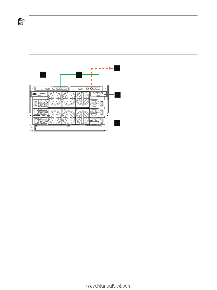
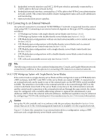
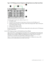
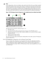
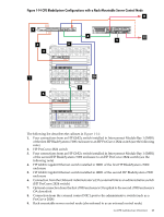
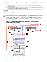
Note: In all configurations with a server blade as the control node, NIC2 of the server blades installed in the same enclosure as the control node will also be connected to the switch used to provide external connectivity. Cluster management software or the system administrator for the cluster must determine what steps are necessary to provide appropriate connectivity to the external network. In a typical installation, NIC2 of the server blades installed in the c3000 enclosure with the control node will be turned off. Contact an HP representative for additional information. Figure 1-13 CP Workgroup System Configuration with a Double-Density Server Blade Control Node 3 1 2 4 5 The following list describes the callouts in Figure 1-13: 1. HP GbE2c switch 2. Connection from the Onboard Administrator's iLO port to the HP GbE2c port 22 3. Optional connection from an HP GbE2c installed in IMB2 to an external network (for example, a campus network) 4. Onboard Administrator module 5. HP BladeSystem c3000 enclosure See Appendix B for the origin and destination cabling tables for the cables used in CP Workgroup System configurations. 1.4.6.3 CPE BladeSystem Configurations with an External Control Node Figure 1-14 shows the connections to an external network when the configuration includes a rack-mountable server control node (also referred to as an external control node). Figure 1-14 shows a configuration with two c7000 enclosures, but the connection scheme applies to all configurations based on either c3000 or c7000 enclosures when a rack-mountable server is used as a control node. 28 Cluster Platform Express Overview
-
 1
1 -
2
-
3
-
4
-
5
-
6
-
7
-
8
-
9
-
10
-
11
-
12
-
13
-
14
-
15
-
16
-
17
-
18
-
19
-
20
-
21
-
22
-
 23
23 -
 24
24 -
 25
25 -
 26
26 -
 27
27 -
 28
28 -
 29
29 -
 30
30 -
 31
31 -
 32
32 -
 33
33 -
34
-
35
-
36
-
37
-
38
-
39
-
40
-
41
-
42
-
43
-
44
-
45
-
46
-
47
-
48
-
49
-
50
-
51
-
52
-
53
-
54
-
55
-
56
-
57
-
58
-
59
-
60
-
61
-
62
-
63
-
64
-
65
-
66
-
67
-
68
-
69
-
70
-
71
-
72
-
73
-
74
-
75
-
76
-
77
-
78
-
79
-
80
-
81
-
82
-
83
-
84
-
85
-
86
-
87
-
88
-
89
-
90
-
91
-
92
-
93
-
94
-
95
-
96
-
97
-
98
-
99
-
100
-
101
-
102
-
103
-
104
-
105
-
106
-
107
-
108
-
109
-
110
-
111
-
112
-
113
-
114
-
115
-
116
-
117
-
118
-
119
-
120
-
121
-
122
-
123
-
124
-
125
-
126
-
127
-
128
-
129
-
130
 |
 |