HP Cluster Platform Express v2010 Workgroup System and Cluster Platform Expres - Page 57
A ProLiant DL3
 |
View all HP Cluster Platform Express v2010 manuals
Add to My Manuals
Save this manual to your list of manuals |
Page 57 highlights
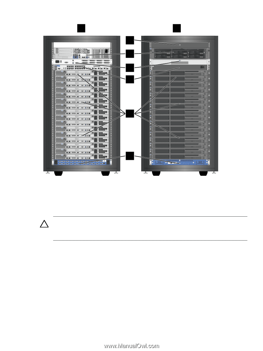
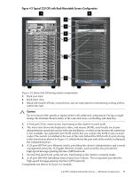
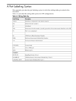
Figure 4-2 Typical 22U CPE with Rack-Mountable Servers Configuration 1 2 Tape 11 33 55 00 22 44 PCI-X 3 2 iLO 2 1 SCSI Port 1 UID 1 3 5 7 Mouse Serial A Video 2 4 6 8 Keybd DL140 G2 1 2 UID LO100i DL140 G2 1 2 UID LO100i DL140 G2 1 2 UID LO100i DL140 G2 1 2 UID LO100i DL140 G2 1 2 UID LO100i DL140 G2 1 2 UID LO100i DL140 G2 1 2 UID LO100i DL140 G2 1 2 UID LO100i DL140 G2 1 2 UID LO100i DL140 G2 1 2 UID LO100i DL140 G2 1 2 UID LO100i DL140 G2 1 2 UID LO100i DL140 G2 1 2 UID LO100i DL140 G2 1 2 UID LO100i DL140 G2 1 2 UID LO100i DL140 G2 PORT 13 1 PORT 14 PORT 15 2 UID PORT 16 PORT 17 PORT 18 PORT 19 PORT 20 LO100i PORT 21 PORT 22 PORT 23 PORT 24 PORT 1 PORT 2 PORT 3 PORT 4 PORT 5 PORT 6 PORT 7 PORT 8 PORT 9 PORT 10 PORT 11 PORT 12 3 4 5 6 7 8 K N L Simplex Duplex ch 1 ch 2 hp ProLiant DL380 G4 1 2 UID Reset 10/100 1 Serial 10/100 0 T C A Figure 4-2 shows the following cluster components: 1. Rack rear view. 2. Rack front view. 3. Blank filler panels fill any unused slots, and are important for maintaining cooling airflow within the rack. Caution: Do not remove filler panels or replace them with additional components. Doing so might change the thermal characteristics of the rack and cause overheating and data loss. 4. A ProLiant DL3xx-series server, functioning as the cluster's control node. 5. The front view shows the keyboard, video, and mouse (KVM), used locally for cluster administration operations such as software installation, or when a remote network connection is not available. An optional 8-port KVM switch lets you connect the KVM to one or more nodes. This switch is installed at the rear of the rack, behind the KVM with its ports facing to the front (not as shown in Figure 4-2, which shows the port side of the switch, to illustrate the component ports.) 6. A 24-port HP ProCurve Ethernet switch, providing the cluster's administrative and console management networks. In Gigabit Ethernet clusters, such switches also provide the high-speed message-passing interface (MPI) network. 7. Several ProLiant DL14x-series servers, functioning as the cluster's compute nodes. 8. A 24-port ISR 9024 InfiniBand interconnect from Voltaire. This component provides the high-speed message-passing interface (MPI) network. Components not shown in Figure 4-2 include: 4.2 CPE with Rack-Mountable Servers - 22U Rack Configuration 57
-
 1
1 -
2
-
3
-
4
-
5
-
6
-
7
-
8
-
9
-
10
-
11
-
12
-
13
-
14
-
15
-
16
-
17
-
18
-
19
-
20
-
21
-
22
-
23
-
24
-
25
-
26
-
27
-
28
-
29
-
30
-
31
-
32
-
33
-
34
-
35
-
36
-
37
-
38
-
39
-
40
-
41
-
42
-
43
-
44
-
45
-
46
-
47
-
48
-
49
-
50
-
51
-
 52
52 -
 53
53 -
 54
54 -
 55
55 -
 56
56 -
 57
57 -
 58
58 -
 59
59 -
 60
60 -
 61
61 -
 62
62 -
63
-
64
-
65
-
66
-
67
-
68
-
69
-
70
-
71
-
72
-
73
-
74
-
75
-
76
-
77
-
78
-
79
-
80
-
81
-
82
-
83
-
84
-
85
-
86
-
87
-
88
-
89
-
90
-
91
-
92
-
93
-
94
-
95
-
96
-
97
-
98
-
99
-
100
-
101
-
102
-
103
-
104
-
105
-
106
-
107
-
108
-
109
-
110
-
111
-
112
-
113
-
114
-
115
-
116
-
117
-
118
-
119
-
120
-
121
-
122
-
123
-
124
-
125
-
126
-
127
-
128
-
129
-
130
 |
 |