HP Cluster Platform Express v2010 Workgroup System and Cluster Platform Expres - Page 27
CPE Workgroup System with Double-Density Server Blades
 |
View all HP Cluster Platform Express v2010 manuals
Add to My Manuals
Save this manual to your list of manuals |
Page 27 highlights
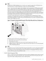
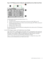
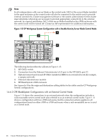
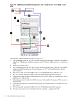
Figure 1-12 CP Workgroup System Configuration with Single-Density Server Blade Control Node 3 1 2 4 5 The following list describes the callouts in Figure 1-12: 1. HP GbE2c switch 2. Connection from the Onboard Administrator's iLO port to the HP GbE2c port 22 3. Optional connection from a server blade control node through an HP GbE2c external port to an external campus network. 4. Onboard Administrator module 5. HP BladeSystem c3000 enclosure See Appendix B for the origin and destination cabling tables for the cables used in CP Workgroup System configurations. 1.4.6.2 CPE Workgroup System with Double-Density Server Blades If the control node is a double-density server blade, server 1 is designated as the control node. NIC2 of server 1 is routed to IMB2 and connectivity to an external network is provided by an HP GbE2C switch installed in IMB2 in the HP BladeSystem c3000 enclosure. If external connectivity to a network is not required this switch may be omitted. Figure 1-13 shows the connection to an external network for a configuration using a c3000 enclosure and a double-density server blade control node. 1.4 CPE Architecture Overview 27
-
 1
1 -
2
-
3
-
4
-
5
-
6
-
7
-
8
-
9
-
10
-
11
-
12
-
13
-
14
-
15
-
16
-
17
-
18
-
19
-
20
-
21
-
 22
22 -
 23
23 -
 24
24 -
 25
25 -
 26
26 -
 27
27 -
 28
28 -
 29
29 -
 30
30 -
 31
31 -
 32
32 -
33
-
34
-
35
-
36
-
37
-
38
-
39
-
40
-
41
-
42
-
43
-
44
-
45
-
46
-
47
-
48
-
49
-
50
-
51
-
52
-
53
-
54
-
55
-
56
-
57
-
58
-
59
-
60
-
61
-
62
-
63
-
64
-
65
-
66
-
67
-
68
-
69
-
70
-
71
-
72
-
73
-
74
-
75
-
76
-
77
-
78
-
79
-
80
-
81
-
82
-
83
-
84
-
85
-
86
-
87
-
88
-
89
-
90
-
91
-
92
-
93
-
94
-
95
-
96
-
97
-
98
-
99
-
100
-
101
-
102
-
103
-
104
-
105
-
106
-
107
-
108
-
109
-
110
-
111
-
112
-
113
-
114
-
115
-
116
-
117
-
118
-
119
-
120
-
121
-
122
-
123
-
124
-
125
-
126
-
127
-
128
-
129
-
130
 |
 |
