HP Cluster Platform Express v2010 Workgroup System and Cluster Platform Expres - Page 18
Fast-Ethernet Network Switches and the Optional InfiniBand Network
 |
View all HP Cluster Platform Express v2010 manuals
Add to My Manuals
Save this manual to your list of manuals |
Page 18 highlights
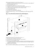
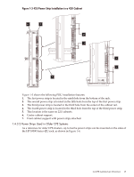
Figure 1-4 42U Power Strip Installation 1 3 2 7 8 6 4 10 9 5 11 The following list describes the callouts shown in Figure 1-4: 1. M5 screw attached to power strip. 2. M5 screw attached to cable management bracket. 3. Power strip mounting plate. 4. Bracket attaching the power strip to the power strip mounting plate. 5. Power strip mounting plate. Attach to right side of rack (looking in from the rear of the rack). 6. Mounting hole location on cable management plate. 7. Seventh hole from right on mounting bracket. 8. Third hole from right on mounting bracket. 9. Insert pin in fifth hole from right on mounting bracket. 10. Insert pin in first hole from left on mounting bracket. 11. Hole mounting locations (viewed from the right side of the rack). See the HP Cluster Platform Core Components Overview for more information. 1.4.4 Fast-Ethernet Network Switches and the Optional InfiniBand Network Your HP Cluster Platform Express includes Fast-Ethernet switches and an optional InfiniBand high-speed network. Section 1.4.4.1 describes the Fast-Ethernet network components, and Section 1.4.4.2 describes the components used for the optional InfiniBand network. 18 Cluster Platform Express Overview
-
 1
1 -
2
-
3
-
4
-
5
-
6
-
7
-
8
-
9
-
10
-
11
-
12
-
 13
13 -
 14
14 -
 15
15 -
 16
16 -
 17
17 -
 18
18 -
 19
19 -
 20
20 -
 21
21 -
 22
22 -
 23
23 -
24
-
25
-
26
-
27
-
28
-
29
-
30
-
31
-
32
-
33
-
34
-
35
-
36
-
37
-
38
-
39
-
40
-
41
-
42
-
43
-
44
-
45
-
46
-
47
-
48
-
49
-
50
-
51
-
52
-
53
-
54
-
55
-
56
-
57
-
58
-
59
-
60
-
61
-
62
-
63
-
64
-
65
-
66
-
67
-
68
-
69
-
70
-
71
-
72
-
73
-
74
-
75
-
76
-
77
-
78
-
79
-
80
-
81
-
82
-
83
-
84
-
85
-
86
-
87
-
88
-
89
-
90
-
91
-
92
-
93
-
94
-
95
-
96
-
97
-
98
-
99
-
100
-
101
-
102
-
103
-
104
-
105
-
106
-
107
-
108
-
109
-
110
-
111
-
112
-
113
-
114
-
115
-
116
-
117
-
118
-
119
-
120
-
121
-
122
-
123
-
124
-
125
-
126
-
127
-
128
-
129
-
130
 |
 |
