HP Cluster Platform Express v2010 Workgroup System and Cluster Platform Expres - Page 23
Cable Management Plate
 |
View all HP Cluster Platform Express v2010 manuals
Add to My Manuals
Save this manual to your list of manuals |
Page 23 highlights
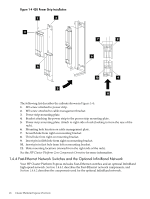
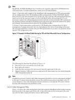
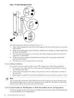
Note: The HP BLc 4X DDR InfiniBand Gen 2 Switch is not currently supported in HP BladeSystem c3000 enclosures. For more information, contact your HP representative. Figure 1-9 provides and example of the InfiniBand cable management in CPE rack-mountable server configurations. Note the InfiniBand cables running from a Voltaire ISR 9024D, 24-port interconnect to each rack-mounted server in the rack. Also, note the cable management brackets used to provide the necessary support for the InfiniBand cables during shipment. It is not necessary to remove the cable management brackets after the system is installed. HP recommends leaving these brackets installed to maintain good connections, provide strain relief for the cables, and maintain the minimum bend radius for the InfiniBand cables. A Voltaire 24-port interconnect can be used in CPE BladeSystem configurations for fabric management. Configuration rules can vary depending on the choice of operating system and also customer preference. Consult with your HP representative if you have any questions about specific CPE configuration rules. Figure 1-9 Example InfiniBand Cable Routing for CPE with Rack-Mountable Server Configurations 3 2 4 1 The following list describes the callouts in Figure 1-9: 1. Direction of view, towards the rear of the rack. 2. Rear right rack column. 3. Cable bundles running to the interconnect from the upper part of the rack. 4. Support brackets. Cables from servers adjacent to the interconnect are not routed along the cable management plate (3). Note: It might be necessary to remove the cable management brackets to service components installed in the rack. To remove these brackets, reverse the installation procedures described in the HP Cluster Platform c-Class Cable Management Bracket Installation Guide and the HP Cluster Platform 24-Node Cable Management Kit Installation Guide. 1.4.4.3 Cable Management Plate Figure 1-10 shows the cable management plate that supports InfiniBand cable bundles running from the nodes in the upper part of the rack, to the interconnect in the lower part of the rack. Use only the fabric straps provided to secure cable bundles. 1.4 CPE Architecture Overview 23
-
 1
1 -
2
-
3
-
4
-
5
-
6
-
7
-
8
-
9
-
10
-
11
-
12
-
13
-
14
-
15
-
16
-
17
-
 18
18 -
 19
19 -
 20
20 -
 21
21 -
 22
22 -
 23
23 -
 24
24 -
 25
25 -
 26
26 -
 27
27 -
 28
28 -
29
-
30
-
31
-
32
-
33
-
34
-
35
-
36
-
37
-
38
-
39
-
40
-
41
-
42
-
43
-
44
-
45
-
46
-
47
-
48
-
49
-
50
-
51
-
52
-
53
-
54
-
55
-
56
-
57
-
58
-
59
-
60
-
61
-
62
-
63
-
64
-
65
-
66
-
67
-
68
-
69
-
70
-
71
-
72
-
73
-
74
-
75
-
76
-
77
-
78
-
79
-
80
-
81
-
82
-
83
-
84
-
85
-
86
-
87
-
88
-
89
-
90
-
91
-
92
-
93
-
94
-
95
-
96
-
97
-
98
-
99
-
100
-
101
-
102
-
103
-
104
-
105
-
106
-
107
-
108
-
109
-
110
-
111
-
112
-
113
-
114
-
115
-
116
-
117
-
118
-
119
-
120
-
121
-
122
-
123
-
124
-
125
-
126
-
127
-
128
-
129
-
130
 |
 |
