HP Cluster Platform Express v2010 Workgroup System and Cluster Platform Expres - Page 31
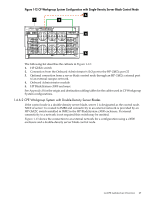
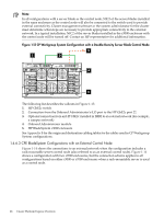
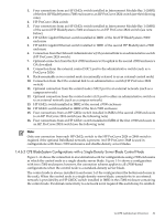
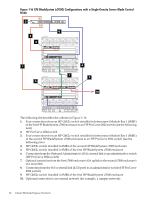
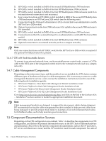
CPE BladeSystem Configurations with a Single-Density Server Blade Control Node
 |
View all HP Cluster Platform Express v2010 manuals
Add to My Manuals
Save this manual to your list of manuals |
Page 31 highlights
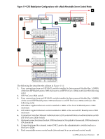
1. Four connections from an HP GbE2c switch installed in Interconnect Module Bay 1 (IMB1) of the first HP BladeSystem c7000 enclosure to an HP ProCurve 2824 switch (see the following note) 2. HP ProCurve 2824 switch 3. Four connections from an HP GbE2c switch installed in Interconnect Module Bay 1 (IMB1) of the second HP BladeSystem c7000 enclosure to an HP ProCurve 2824 switch (see note below) 4. HP GbE2c Gigabit Ethernet switch installed in IMB1 of the first HP BladeSystem c7000 enclosure 5. HP GbE2c Gigabit Ethernet switch installed in IMB1 of the second HP BladeSystem c7000 enclosure 6. Connection from the Onboard Administrator's (OA) external link to an administrative switch (HP ProCurve 2824 switch) 7. Optional connection from the first c7000 enclosure's OA uplink to the second c7000 enclosure's OA downlink 8. Connection from the external control NIC1 port to the administrative switch (such as a ProCurve 2824) 9. Rack-mountable server control node (occasionally referred to as an external control node) 10. Connection from the OA's external link to an administrative switch (HP ProCurve 2824 switch) 11. Optional connection from the control node's NIC2 port to an external network (such as a campus network) 12. Optional connection from the control node's iLO port to either an administrative switch or to an external network (such as a campus network) 13. HP GbE2c switch installed in IMB2 of the second c7000 enclosure 14. HP GbE2c switch installed in IMB2 of the first c7000 enclosure 15. Four connections from an HP GbE2c switch installed in IMB2 of the second c7000 enclosure to an HP ProCurve 2824 switch (see the following note) 16. Four connections from an HP GbE2c switch installed in IMB2 of the first c7000 enclosure to an HP ProCurve 2824 switch (see the following note) Note: Only one connection from each HP GbE2c switch to the HP ProCurve 2824 or 2848 switch is required if the optional InfiniBand network is present. An HP ProCurve 2848 is used in configurations with three c7000 enclosures and double-density server blades. 1.4.6.5 CPE BladeSystem Configurations with a Single-Density Server Blade Control Node Figure 1-16 shows the connection to an external network for configurations using c7000 enclosures in which the control node is a single-density server blade. Figure 1-16 shows a configuration with two c7000 enclosures; however, the connection scheme applies to all c7000-based configurations when the control node is a standard-density server blade. The control node is always installed in enclosure 1 of the configuration (the bottom enclosure in the rack). When the control node is a single-density server blade, connectivity to an external network is provided by an HP GbE2C switch installed in IMB2 in the c7000 enclosure containing the control node. If external connectivity to a network is not required this switch may be omitted. 1.4 CPE Architecture Overview 31
-
 1
1 -
2
-
3
-
4
-
5
-
6
-
7
-
8
-
9
-
10
-
11
-
12
-
13
-
14
-
15
-
16
-
17
-
18
-
19
-
20
-
21
-
22
-
23
-
24
-
25
-
 26
26 -
 27
27 -
 28
28 -
 29
29 -
 30
30 -
 31
31 -
 32
32 -
 33
33 -
 34
34 -
 35
35 -
 36
36 -
37
-
38
-
39
-
40
-
41
-
42
-
43
-
44
-
45
-
46
-
47
-
48
-
49
-
50
-
51
-
52
-
53
-
54
-
55
-
56
-
57
-
58
-
59
-
60
-
61
-
62
-
63
-
64
-
65
-
66
-
67
-
68
-
69
-
70
-
71
-
72
-
73
-
74
-
75
-
76
-
77
-
78
-
79
-
80
-
81
-
82
-
83
-
84
-
85
-
86
-
87
-
88
-
89
-
90
-
91
-
92
-
93
-
94
-
95
-
96
-
97
-
98
-
99
-
100
-
101
-
102
-
103
-
104
-
105
-
106
-
107
-
108
-
109
-
110
-
111
-
112
-
113
-
114
-
115
-
116
-
117
-
118
-
119
-
120
-
121
-
122
-
123
-
124
-
125
-
126
-
127
-
128
-
129
-
130
 |
 |
