HP Portable 386 Compaq Portable 386 Personal Computer Maintenance and Service
HP Portable 386 - Notebook PC Manual
 |
View all HP Portable 386 manuals
Add to My Manuals
Save this manual to your list of manuals |
HP Portable 386 manual content summary:
- HP Portable 386 | Compaq Portable 386 Personal Computer Maintenance and Service - Page 1
. The strap is not necessary if a shielded cable connects the two chassis. COMPAQ PORTABLE 386 PERSONAL COMPUTER MAINTENANCE AND SERVICE GUIDE is a troubleshooting guide that can be used as a reference when servicing the COMPAQ PORTABLE 386 Personal Computer. Compaq Computer Corporation reserves - HP Portable 386 | Compaq Portable 386 Personal Computer Maintenance and Service - Page 2
make changes in its COMPAQ PORTABLE 386 Personal Computer without notice. Accordingly, the diagrams and procedures in this document may not apply to the computer you are servicing. CAUTION Only trained technicians should attempt to repair this equipment. All troubleshooting and repair procedures - HP Portable 386 | Compaq Portable 386 Personal Computer Maintenance and Service - Page 3
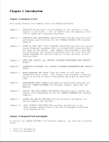
problems that can occur with the COMPAQ PORTABLE 386 Personal Computer during the Power On Self Test procedure. Chapter 4. SETUP AND INSPECT (See SUPPORT SOFTWARE MAINTENANCE AND SERVICE GUIDE.) Chapter 5. DIAGNOSTICS PROGRAM (See SUPPORT SOFTWARE MAINTENANCE AND SERVICE GUIDE.) Chapter - HP Portable 386 | Compaq Portable 386 Personal Computer Maintenance and Service - Page 4
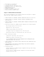
software are available to support these and other COMPAQ computer products: o COMPAQ PORTABLE 386 PERSONAL COMPUTER OPERATIONS GUIDE (PN 107918-001) o COMPAQ PORTABLE 386 PERSONAL COMPUTER TECHNICAL REFERENCE GUIDE (PN 107920-001) o COMPAQ PORTABLE 386 PERSONAL COMPUTER MEMORY EXPANSION INSTALLATION - HP Portable 386 | Compaq Portable 386 Personal Computer Maintenance and Service - Page 5
PN 114496-001) o MS-DOS VERSION 3 REFERENCE GUIDE (PN 114024-001) o BASIC VERSION 3 REFERENCE GUIDE (PN 104030-001) o MICROSOFT Operating System/2 Standard Version 1.1 o Service Advisories and Bulletins o HOW TO DO BUSINESS WITH COMPAQ SERVICE o COMPAQ SERVICE QUICK REFERENCE GUIDE (PN 106854-001) - HP Portable 386 | Compaq Portable 386 Personal Computer Maintenance and Service - Page 6
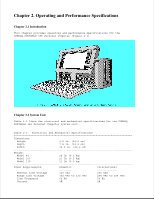
chapter provides operating and performance specifications for the COMPAQ PORTABLE 386 Personal Computer (Figure 2-1). Chapter 2.2 System Unit Table 2-1 lists the electrical and mechanical specifications for the COMPAQ PORTABLE 386 Personal Computer system unit. Table 2-1. Electrical and Mechanical - HP Portable 386 | Compaq Portable 386 Personal Computer Maintenance and Service - Page 7
(9100 m) Chapter 2.3 Portable Enhanced Keyboard Table 2-2 lists the specifications for the portable enhanced keyboard. Table 2-2. Interface Industry standard 5 pin circular DIN type connector Chapter 2.4 Compaq Dual Mode Plasma Display Table 2-3 lists the specifications for the - HP Portable 386 | Compaq Portable 386 Personal Computer Maintenance and Service - Page 8
200 320 x 200 Text Resolution 640 x 400 (80 characters x 25 lines) Chapter 2.5 1.2 Megabyte Diskette Drive Table 2-4 lists specifications for the 1.2 megabyte diskette drive. Table 2-4. 1.2 Megabyte Diskette Drive Specifications Dimensions: Height 1.1 in. (2.8 cm) Depth 8.0 in. (20 - HP Portable 386 | Compaq Portable 386 Personal Computer Maintenance and Service - Page 9
(720 Kbyte format) Bytes per Sector 512 Chapter 2.8 40 Megabyte Fixed Disk Drive Table 2-7 lists the specifications for the 40 megabyte fixed disk drive. Table 2-7. 40 Megabyte Fixed Disk Drive Specifications Dimensions: Height 1.5 in. (3.8 cm) Depth 4.0 in. (10.2 cm) Width 5.8 in - HP Portable 386 | Compaq Portable 386 Personal Computer Maintenance and Service - Page 10
Mb/s Interleave 1:1 for Drive Type 43 3:1 for Drive Type 17 Chapter 2.9 100 Megabyte Fixed Disk Drive Table 2-8 lists the specifications 4.0 in. (10.2 cm) Weight 2.9 lb. (1.9 kg) Drive Type (used in SETUP program) 45 Media: Number of Surfaces 8 Tracks per Surface 748 Number - HP Portable 386 | Compaq Portable 386 Personal Computer Maintenance and Service - Page 11
cm) Weight 1.8 lb (0.81 kg) Drive Type 33 (Used in SETUP program) Number of Logical Data Heads 8 Number of Logical Cylinders 832 Average Access Time less than 25 ms Data Transfer Rate 10 Mb/s Sectors per Track 33 Interleave 1:1 Chapter 2.11 Compaq 1200 Baud Internal Modem Table - HP Portable 386 | Compaq Portable 386 Personal Computer Maintenance and Service - Page 12
8 bit expansion boards will not fit. Chapter 2.14 40 Megabyte Tape Drive Expansion Unit Table 2-13 lists the specifications for the 40 megabyte tape drive expansion unit. Table 2-13. 40 Megabyte Tape Drive Expansion Unit Specifications Dimensions: Height 6.0 in. (15.2 cm) Depth 2.4 in - HP Portable 386 | Compaq Portable 386 Personal Computer Maintenance and Service - Page 13
Expansion Unit Table 2-15 lists the specifications for the 300/600 Megabyte Fixed Disk Drive Expansion Unit. Table 2-15. 300/600 Megabyte Fixed Disk Drive Expansion Unit Specifications Dimensions: Height 6.4 in. (16.1 cm) Depth 16.5 in. (41.9 cm) Width 14.5 in. (35.9 cm) Weight - HP Portable 386 | Compaq Portable 386 Personal Computer Maintenance and Service - Page 14
in one 8/16 bit expansion slot in the system unit. External Interface Adapter External interface adapter supports one or two 300 megabyte fixed disk drives LED Indicator Green Power Requirements: U.S. International ---- Nominal Line Voltage 120 VAC, 60 Hz 230 VAC, 50 - HP Portable 386 | Compaq Portable 386 Personal Computer Maintenance and Service - Page 15
problem isolation procedures and a flowchart for quick reference. Chapter 3.1 POST POST is a series of diagnostic tests that automatically run on the COMPAQ PORTABLE 386 Personal Computer Diskette drives o Fixed disk drives POST also detects the type of mass storage devices installed in the computer. - HP Portable 386 | Compaq Portable 386 Personal Computer Maintenance and Service - Page 16
of the COMPAQ DIAGNOSTICS diskette into Drive A (Drive Position 1), and push in on the drive button. 8. Turn on the computer. See the SUPPORT SOFTWARE MAINTENANCE AND SERVICE GUIDE for detailed information on problem isolation. Chapter 3.3 Problem Isolation Flowchart The problem isolation flowchart - HP Portable 386 | Compaq Portable 386 Personal Computer Maintenance and Service - Page 17
- HP Portable 386 | Compaq Portable 386 Personal Computer Maintenance and Service - Page 18
- HP Portable 386 | Compaq Portable 386 Personal Computer Maintenance and Service - Page 19
- HP Portable 386 | Compaq Portable 386 Personal Computer Maintenance and Service - Page 20
Chapter 4. Setup and Inspect Chapter 4.0 Introduction Please consult the SUPPORT SOFTWARE MAINTENANCE AND SERVICE GUIDE for current information on SETUP and INSPECT. - HP Portable 386 | Compaq Portable 386 Personal Computer Maintenance and Service - Page 21
Chapter 5. Diagnostics Program Chapter 5.0 Introduction Please consult the SUPPORT SOFTWARE MAINTENANCE AND SERVICE GUIDE for current information on DIAGNOSTICS. - HP Portable 386 | Compaq Portable 386 Personal Computer Maintenance and Service - Page 22
. Chapter 6.2 Power On Self Test Messages An error message results if a problem is encountered during the Power On Self Test. This Power On Self Test runs 2 Short System Check memory configuration Error configuration and run SETUP. incorrect XX000YY ZZ - 201 None RAM failure Refer to - HP Portable 386 | Compaq Portable 386 Personal Computer Maintenance and Service - Page 23
None Fixed disk drive Run DIAGNOSTICS. Controller Failure controller error 1790 - Disk 0 None Fixed disk drive 1. Run SETUP. Failure 2. DIAGNOSTIC error codes occur if the system recognizes a problem while running the COMPAQ DIAGNOSTICS Program. These error codes help identify possible - HP Portable 386 | Compaq Portable 386 Personal Computer Maintenance and Service - Page 24
or AA represents the faulty subassembly. YY denotes the test or action that failed. XX denotes a specific problem. For example, error code 603 - 07 indicates that the diskette drive write/read/compare test failed. For assistance in the removal and replacement of a particular subassembly, see Chapter - HP Portable 386 | Compaq Portable 386 Personal Computer Maintenance and Service - Page 25
test failed and retest. 102 - 11 Numeric coprocessor speed test failed 102 - 12 Numeric coprocessor pattern test failed 102 - 14 Switch indicates no coprocessor present 102 - 15 Coprocessor is inoperative or socket is unoccupied Error Code Error Description Recommended Action 103 - HP Portable 386 | Compaq Portable 386 Personal Computer Maintenance and Service - Page 26
test Replace the system board and retest failed. for error codes 103 - 01 through 113 - 01. 109 - 02 CMOS clock rollover test failed. 109 - 03 CMOS clock test, CMOS not properly initialized. 110 - 01 Programmable timer load data test failed. 110 - 02 Programmable timer dynamic test failed - HP Portable 386 | Compaq Portable 386 Personal Computer Maintenance and Service - Page 27
and retest. 199 - 00 Installed devices test 1. Check system configuration. failed. 2. Verify cable connections. 3. Check switch settings. 4. Run SETUP. 5. Replace system board and retest. Table 6-3. Memory Error Codes (2xx - xx Range) Error Code Error Description Recommended - HP Portable 386 | Compaq Portable 386 Personal Computer Maintenance and Service - Page 28
short test, echo test failed 301 - 04 Keyboard short test, keyboard retest failed. 1. Check the keyboard connector. If disconnected, turn off the computer and connect the keyboard. 2. Replace the keyboard and retest. 3. Replace the system board and retest. 302 - 01 Keyboard long test failed. - HP Portable 386 | Compaq Portable 386 Personal Computer Maintenance and Service - Page 29
command byte restore test failed. 303 - 09 Keyboard LED test, LEDs failed to light. 1. Check the keyboard connector. If disconnected, turn off the computer and connect the keyboard. 2. Replace the keyboard and retest. 3. Replace the system board and retest. 304 - 01 Keyboard repeat key test failed - HP Portable 386 | Compaq Portable 386 Personal Computer Maintenance and Service - Page 30
402 - 03 Printer data and control registers failed. 402 - 04 Printer loopback failed. 402 - 05 Printer loopback and data registers failed. 3. Replace the Serial/Parallel Interface Board, if applicable, and retest. 4. Replace the printer and/or the printer cable and retest. 5. Replace the system - HP Portable 386 | Compaq Portable 386 Personal Computer Maintenance and Service - Page 31
the system board and retest. 506 - 01 Video 80 x 25 mode 8 x 8 character cell test failed. 507 - 01 Video 40 x 25 mode test failed. 508 - 01 Video 320 x 200 mode Diskette Drive Error Codes (6xx - xx Range) Error Code Error Description Recommended Action 600 - xx Diskette Drive ID - HP Portable 386 | Compaq Portable 386 Personal Computer Maintenance and Service - Page 32
controller 601 - 09 Failed to format a track 601 - 23 Failed to set drive type in ID media 602 - xx Diskette Read Test the system board and retest 604 - 02 Exceeded maximum hard error limit 604 - 03 Previously exceeded soft error limit 604 - 04 Previously exceeded hard error limit 604 - 05 - HP Portable 386 | Compaq Portable 386 Personal Computer Maintenance and Service - Page 33
ID Media Test 605 - 20 Failed to get drive type 605 - 24 Failed to read diskette media 605 - 25 Failed to verify diskette media 606 - xx Diskette type error. 698 - 00 Diskette drive speed not within limits 699 - 00 Drive/media ID error; rerun SETUP Table 6-8. Monochrome Video Board Error Codes - HP Portable 386 | Compaq Portable 386 Personal Computer Maintenance and Service - Page 34
. 1101 - 10 COM1 set to interrupt 3. 1101 - 11 COM2 set to interrupt 4. 1101 - 12 Drive/receiver control signal failed. 1101 - 13 UART control signal interrupt failed. 1101 - 14 Drive/receiver data failed. Error Code Error Description Recommended Action 1109 - 01 Clock register The - HP Portable 386 | Compaq Portable 386 Personal Computer Maintenance and Service - Page 35
Error Code Error Description Recommended Action 1201 - xx Modem Internal Loopback Test The following steps apply to error codes 1201 - 01 through 1210 - 11: 1201 - 01 UART DLAB bit failed. 1. Check the jumper settings on 1201 - 02 Line input or UART failed. the system board (see Chapter - HP Portable 386 | Compaq Portable 386 Personal Computer Maintenance and Service - Page 36
1203 - 01 Modem external TIP/RING failed. 1203 - 02 Modem external DATA TIP/RING failed. 1203 - 03 Modem line termination failed. Error Code Error Description Recommended Action 1204 - xx Modem Auto Originate Test The following steps apply to error codes 1201 - 01 through 1210 - 11 - HP Portable 386 | Compaq Portable 386 Personal Computer Maintenance and Service - Page 37
retry limit. 1205 - 04 RCV exceeded carrier lost limit. 1205 - 05 XMIT exceeded carrier lost limit. 1205 - 06 Time out waiting for dial tone. 5. Replace the system board and retest. 1205 - 07 Dial number string too long. 1205 - 08 Modem timed out waiting for remote response. 1205 - 09 Modem - HP Portable 386 | Compaq Portable 386 Personal Computer Maintenance and Service - Page 38
1701 - 09 Failed to format a cylinder settings and retest (see Chapter 9, "Jumper and Switch 1701 - 42 Recalibrate fixed disk drive Settings"). failed. 2. Replace the fixed disk drive signal and power cables and 1701 - 58 Failed to write sector retest. buffer. 3. Replace the fixed disk - HP Portable 386 | Compaq Portable 386 Personal Computer Maintenance and Service - Page 39
sector buffer. 1701 - 66 Failed to initialize fixed disk drive parameter. and retest. 4. Replace the system board and retest. 1702 - xx Fixed Disk Drive Read Test 1702 - 01 Exceeded maximum soft error limit. 1702 - 02 Exceeded maximum hard error limit. 1702 - 03 Previously exceeded maximum soft - HP Portable 386 | Compaq Portable 386 Personal Computer Maintenance and Service - Page 40
- xx Fixed Disk Drive Random Seek 4. Replace the system board and Test. retest. 1704 - 01 Exceeded maximum soft error limit. 1704 - 02 Exceeded maximum hard error limit. 1704 - 03 Previously exceeded maximum soft error limit. 1704 - 04 Previously exceeded maximum hard error limit. 1704 - 05 - HP Portable 386 | Compaq Portable 386 Personal Computer Maintenance and Service - Page 41
1717 - 73: 1706 - 41 Drive not ready. 1. Check the system board jumper 1707 - xx Fixed Disk Drive Recalibrate settings and retest Test (see fixed disk drive disk drive. signal and power cables and retest. 1708 - xx Fixed Disk Drive Format Bad 3. Replace the fixed disk drive Track Test - HP Portable 386 | Compaq Portable 386 Personal Computer Maintenance and Service - Page 42
signal and power cables and retest. 3. Replace the fixed disk drive and retest. 4. Replace the system board and retest. 1714 - 01 Exceeded maximum soft error limit. 1714 - 02 Exceeded maximum hard error limit. 1714 - 03 Previously exceeded maximum soft error limit. 1714 - 04 Previously exceeded - HP Portable 386 | Compaq Portable 386 Personal Computer Maintenance and Service - Page 43
signal and power cables and type. retest. 3. Replace the fixed disk drive 1714 - 24 Failed to read diskette media. and retest. 4. Replace the system board and 1714 - 25 Failed to verify diskette retest. media. 1714 - 40 Cylinder 0 error. 1714 - 48 Failed to move disk table to RAM. 1714 - HP Portable 386 | Compaq Portable 386 Personal Computer Maintenance and Service - Page 44
Code Error Description Recommended Action 1716 - xx Fixed Disk Drive Conditional The following steps apply to error Format Test codes 1700 - xx through 1717 - 73: 1716 - 01 Exceeded maximum soft error limit. 1716 - 02 Exceeded maximum hard error limit. 1716 - 05 Failed to reset controller - HP Portable 386 | Compaq Portable 386 Personal Computer Maintenance and Service - Page 45
1717 - xx Fixed Disk Drive ECC Test 1717 - 01 Exceeded maximum soft error limit. 1717 - 02 Exceeded maximum hard error limit. Error Code Error Description Recommended Action 1717 - 03 Previously exceeded maximum The following steps apply to error soft error limit. codes 1700 - xx - HP Portable 386 | Compaq Portable 386 Personal Computer Maintenance and Service - Page 46
- 22 Never got to end of tape after servo check. 1. Replace the tape cartridge and retest. 2. Replace the tape drive expansion unit and retest. 3. Replace the system board and retest. 1901 - 25 Unable to erase cartridge. 1901 - 27 Drive not compatible with controller. 1902 - xx Tape Format Test - HP Portable 386 | Compaq Portable 386 Personal Computer Maintenance and Service - Page 47
1991 - xx: 1904 - xx Tape Beginning of Tape/End of Tape Test 1. Replace the tape cartridge and retest. 1904 - 01 Drive not installed. 2. Replace the tape drive expansion unit and retest. 1904 - 02 Cartridge not installed. 3. Replace the system board and retest. 1904 - 03 Tape motion error - HP Portable 386 | Compaq Portable 386 Personal Computer Maintenance and Service - Page 48
limit exceeded. 3. Replace the system board and retest. 1905 - 18 Hard error limit exceeded. 1905 - 19 Write (probably ID error). 1905 - 27 Drive not compatible with controller. 1906 - xx Tape Write, Read, Compare Test 1906 - 01 Drive not installed. 1906 - 02 Cartridge not installed. 1906 - 03 - HP Portable 386 | Compaq Portable 386 Personal Computer Maintenance and Service - Page 49
the tape drive expansion unit and retest. 1906 - 18 Hard error limit drive. 1906 - 27 Drive not compatible with controller. 1991 - 12 Tape has not been servo written. Table 6-13. COMPAQ 2406 - 01 Video 80 x 25 Mode 8 x 8 Character Cell Test 2407 - 01 Video 40 x 25 Mode Test 2408 - 01 - HP Portable 386 | Compaq Portable 386 Personal Computer Maintenance and Service - Page 50
- 01 VGC and ECG monochrome text mode test failed. 2425 - 01 VGC and ECG monochrome graphics mode test failed. Table 6-14. COMPAQ Dual Mode Plasma Display Error Codes (51xx - xx Range) Error Code Error Description Recommended Action 5101 - 01 Video controller Test The following - HP Portable 386 | Compaq Portable 386 Personal Computer Maintenance and Service - Page 51
display and retest. 3. Replace the system board and retest. 5107 - 01 Video 40 x 25 Mode Test 5108 - 01 Video 320 x 200 Mode Color Set 0 Test 5109 - 01 if multiple memory errors are detected. o The problem may be due to a failure in the memory support circuitry, not the memory. The memory error - HP Portable 386 | Compaq Portable 386 Personal Computer Maintenance and Service - Page 52
ZZ). The XX and Y alphanumeric codes are the key identification points for defective memory isolation. Due to the design of the COMPAQ PORTABLE 386 Personal Computer, the remaining codes in the format are not required for determining memory locations. The 8 digit code is defined as follows: XX - HP Portable 386 | Compaq Portable 386 Personal Computer Maintenance and Service - Page 53
- HP Portable 386 | Compaq Portable 386 Personal Computer Maintenance and Service - Page 54
- HP Portable 386 | Compaq Portable 386 Personal Computer Maintenance and Service - Page 55
a third column that provides reference numbers keyed to specific illustrations. Table 7-5 lists spare parts for the various options available for the COMPAQ PORTABLE 386 Personal Computer. Tables 7-6 and 7-7 list parts that are available only in a kit, and each kit has only one part number. Chapter - HP Portable 386 | Compaq Portable 386 Personal Computer Maintenance and Service - Page 56
Table 7-1. Display Enclosure Assembly Item Description Part Number 1. COMPAQ Dual Mode Plasma Display 107381-001 2. Display Filter Assembly 107689-001 3. Display Enclosure 107043-001 4. Keyboard Connector Cover * 107120-001 5. Brightness Control Assembly 107384-001 6. - HP Portable 386 | Compaq Portable 386 Personal Computer Maintenance and Service - Page 57
Enhanced Keyboard Assembly Table 7-2 lists the keyboard assembly for the COMPAQ PORTABLE 386 Personal Computer, which is illustrated in Figure 7-3. Table 7-2. Portable Enhanced Keyboard Assembly Item Description Part Number 1. Keyboard Assembly - Domestic 107672-001 2. Keyboard - HP Portable 386 | Compaq Portable 386 Personal Computer Maintenance and Service - Page 58
Table 7-3 lists the spare parts for the COMPAQ PORTABLE 386 Personal Computer chassis rear assembly. Items numbered 1 through 14 are illustrated in Figure 7-4, and items numbered 15 through 34 are illustrated in Figure 7-5. Table 7-3. Chassis - Rear Assembly - HP Portable 386 | Compaq Portable 386 Personal Computer Maintenance and Service - Page 59
3. Power Supply Ground Subassembly 107624-001 4. Battery 107786-001 5. System Board 107683-001 6. Microprocessor Cover 107791-001 23. 2400 Baud Modem Bezel * 107387-001 24. COMPAQ 1200 Baud Internal Modem 107376-001 25. 1200 Baud Modem Bezel * 107387-001 26. Plasma Display - HP Portable 386 | Compaq Portable 386 Personal Computer Maintenance and Service - Page 60
Assembly Table 7-4 lists the spare parts for the COMPAQ PORTABLE 386 Personal Computer chassis side assembly, which is illustrated in Figure 7-6. Table 7-4. Chassis - Side Assembly Item Description Part Number 1. Drive Bezel 107202-001 (No longer available) 2. 1.2 Megabyte Diskette - HP Portable 386 | Compaq Portable 386 Personal Computer Maintenance and Service - Page 61
-001 12. Drive Cover 107480-001 * Included in the Miscellaneous Hardware Kit (PN 107386-001). ** Included in the Cable Kit (PN 107382-001). Chapter 7.6 Spare Parts for Options Table 7-5 lists spare parts for the options available for the COMPAQ PORTABLE 386 Personal Computer and their - HP Portable 386 | Compaq Portable 386 Personal Computer Maintenance and Service - Page 62
- HP Portable 386 | Compaq Portable 386 Personal Computer Maintenance and Service - Page 63
- HP Portable 386 | Compaq Portable 386 Personal Computer Maintenance and Service - Page 64
- HP Portable 386 | Compaq Portable 386 Personal Computer Maintenance and Service - Page 65
- HP Portable 386 | Compaq Portable 386 Personal Computer Maintenance and Service - Page 66
Table 7-5. Spare Parts for Options Description Part Number 32 Bit Memory/Modem Interface Board 107684-001 1 to 2 Megabyte Memory Expansion Board 107686-001 512 Kbyte Memory Module 107687-001 - HP Portable 386 | Compaq Portable 386 Personal Computer Maintenance and Service - Page 67
-001 4 Megabyte Memory Extension Board 107685-001 COMPAQ 1200 Baud Internal Modem 107376-001 COMPAQ 2400 Baud Internal Modem 107791-001 Second Serial Interface Board (International) 107871-001 Expansion Unit (complete) 107453-001 Tape Drive Expansion Unit 107785-001 Tape Cartridge (40 - HP Portable 386 | Compaq Portable 386 Personal Computer Maintenance and Service - Page 68
) for the COMPAQ PORTABLE 386 and COMPAQ PORTABLE III Personal Computers. Table 7-7. Miscellaneous Hardware Kit Description Quantity Screw - Power Supply/Drive Enclosure 25 Screw - Rear Panel Long 25 Screw - Rear Panel Short 10 Drive Shoulder Bolt 10 Drive Vibration Isolators 10 - HP Portable 386 | Compaq Portable 386 Personal Computer Maintenance and Service - Page 69
various part numbers and locations. After completing all removal and replacement procedures, run the DIAGNOSTICS Program on the COMPAQ PORTABLE 386 Personal Computer to verify the proper operation of the replaced component. Chapter 8.2 Preparation Procedure Before beginning the procedures in this - HP Portable 386 | Compaq Portable 386 Personal Computer Maintenance and Service - Page 70
Section 8.2). 2. Detach the keyboard from the system unit. 3. Grasp the keyboard cord near where it connects to the computer. Gently pull it away from the keyboard connector on the computer (Figure 8-2). 4. Slide the keyboard connector cover off of the keyboard cord and set it aside (Figure 8-3). - HP Portable 386 | Compaq Portable 386 Personal Computer Maintenance and Service - Page 71
side down on a level surface with the rear panel facing upward. 3. Remove the six screws and washers that secure the rear panel to the computer (Figure 8-4). Note that the two screws you removed from the center position are shorter than the other four screws. 4. Carefully pull the rear panel - HP Portable 386 | Compaq Portable 386 Personal Computer Maintenance and Service - Page 72
CAUTION Do not overtighten the screws Chapter 8.5 Interface Connector Cover The interface connector cover protects the 32 bit memory/modem interface connector when nothing is installed in the options compartment. This cover must be removed before either modem, the second serial interface board, - HP Portable 386 | Compaq Portable 386 Personal Computer Maintenance and Service - Page 73
aside (Figure 8-6). To replace the interface connector cover, reverse steps 1 through 5. Chapter 8.6 Microprocessor Cover To remove the microprocessor cover: 1. Complete the preparation procedure (see Section 8.2). 2. Remove the rear panel (see Section 8.4). 3. Locate the microprocessor cover shown - HP Portable 386 | Compaq Portable 386 Personal Computer Maintenance and Service - Page 74
4. Grasp the microprocessor cover at its edges; gently lift it up and away from the system board and set it aside (Figure 8-8). To replace the microprocessor cover, reverse steps 1 through 4. NOTE: Position the cover so that the edges slanted in go inside the fence and those slanted out go outside - HP Portable 386 | Compaq Portable 386 Personal Computer Maintenance and Service - Page 75
that secure the system board cover to the system board assembly and set them aside. 8. Lift the system board cover up and away from the computer and set it aside (Figure 8-10). To replace the system board cover, reverse steps 1 through 8. - HP Portable 386 | Compaq Portable 386 Personal Computer Maintenance and Service - Page 76
Chapter 8.8 32 Bit Memory/Modem Interface Board The 32 bit memory/modem interface board connects the memory expansion boards, either internal modem, and the second serial interface board to the system board. If one or a combination of these options is installed, the 32 bit memory/modem interface - HP Portable 386 | Compaq Portable 386 Personal Computer Maintenance and Service - Page 77
them aside. 5. Grasp the 32 bit memory/modem interface board at its edges and, without rocking it, lift it straight up and away from the computer (Figure 8-12). When the 32 bit memory/modem interface board is removed, the options compartment with its two expansion slots is revealed (Figure 8-13). - HP Portable 386 | Compaq Portable 386 Personal Computer Maintenance and Service - Page 78
second serial interface board or one of the internal modems. Both the COMPAQ 1200 Baud Internal Modem and the COMPAQ 2400 Baud Internal Modem, are approved for use with the COMPAQ PORTABLE 386 Personal Computer. The second slot allows memory expansion using any of three different memory expansion - HP Portable 386 | Compaq Portable 386 Personal Computer Maintenance and Service - Page 79
5. Locate the internal modem and modem ground bracket shown in Figure 8-15. 6. Remove the one screw that secures the modem ground bracket to the system board (Figure 8-16). - HP Portable 386 | Compaq Portable 386 Personal Computer Maintenance and Service - Page 80
7. Remove the modem bezel (Figure 8-17). 8. Slide the internal modem out of the options compartment and set it aside (Figure 8-18). - HP Portable 386 | Compaq Portable 386 Personal Computer Maintenance and Service - Page 81
To replace the internal modem option, reverse steps 1 through 8. Chapter 8.10 Second Serial Interface Board (International Only) To remove the second serial interface board: 1. Complete the preparation procedure (see Section 8.2). 2. Remove the rear panel (see Section 8.4). 3. Remove the 32 bit - HP Portable 386 | Compaq Portable 386 Personal Computer Maintenance and Service - Page 82
5. Locate the second serial interface board shown in Figure 8-20. 6. Slide the second serial interface board out of the options compartment and set it aside (Figure 8-21). - HP Portable 386 | Compaq Portable 386 Personal Computer Maintenance and Service - Page 83
4 megabyte memory expansion board. Each memory expansion board (or combination) fits into the same options compartment slot in the COMPAQ PORTABLE 386 Personal Computer. The diagram on the following for a quick reference to the memory expansion process. NOTE: Memory expansion boards cannot be added - HP Portable 386 | Compaq Portable 386 Personal Computer Maintenance and Service - Page 84
To remove a memory expansion board: 1. Complete the preparation procedure (see Section 8.2). 2. Remove the rear panel (see Section 8.4). 3. Remove the 32 bit memory/modem interface board (see Section 8.8). 4. Press the top tab and disconnect the LED/speaker and keyboard cables from the system board - HP Portable 386 | Compaq Portable 386 Personal Computer Maintenance and Service - Page 85
5. Locate the memory expansion board shown in Figure 8-23. 6. Slide the memory expansion board out of the options compartment and set it aside (Figure 8-24). - HP Portable 386 | Compaq Portable 386 Personal Computer Maintenance and Service - Page 86
(see Section 8.2). 2. Remove the rear panel (see Section 8.4). 3. Remove the system board cover (see Section 8.6). 4. Locate the memory module that is to be replaced (Figure 8-25). - HP Portable 386 | Compaq Portable 386 Personal Computer Maintenance and Service - Page 87
5. To release the module, insert a tool, such as a ball point pen, into the hole at one end of the module. 6. Grasp the end of the module, pull up, and "peel" it away from its socket (Figure 8-26). To replace the memory module, simply reinsert it into its socket, then reverse steps 1 through 3. To - HP Portable 386 | Compaq Portable 386 Personal Computer Maintenance and Service - Page 88
1. Complete the preparation procedure (see Section 8.2). 2. Remove the rear panel (see Section 8.4). 3. Remove the 32 bit memory/modem interface board (see Section 8.8). 4. Remove the 1 to 2 megabyte memory expansion board (see Section 8.11). 5. Locate the memory module that is to be replaced ( - HP Portable 386 | Compaq Portable 386 Personal Computer Maintenance and Service - Page 89
To replace the memory module, simply reinsert it fully into its socket, then reverse steps 1 through 5. Chapter 8.13 System ROM To remove the system ROM CAUTION The ROMs are sensitive to static electricity and are shipped on conductive foam to protect them from accidental electrostatic discharge. - HP Portable 386 | Compaq Portable 386 Personal Computer Maintenance and Service - Page 90
8. Using an IC removal tool, remove the system ROM (Figure 8-30). 9. Using an IC insertion tool, insert the new ROM into the appropriate sockets (Figure 8-31). - HP Portable 386 | Compaq Portable 386 Personal Computer Maintenance and Service - Page 91
expansion board, if installed (see Section 8.11). 10. Disconnect the following cables (shown in Figure 8-32) from the system board: o System board power cable o Diskette drive data cable o Diskette drive power cable o Fixed disk - HP Portable 386 | Compaq Portable 386 Personal Computer Maintenance and Service - Page 92
o Fixed disk drive power cable o LED/speaker cable o Keyboard cable o Display controller board data cable o Battery cable 11. Remove the screws that secure the system board assembly to the main enclosure (Figure 8-33). NOTE: Use a 3/16 inch wrench to remove the standoffs and a Torx screwdriver to - HP Portable 386 | Compaq Portable 386 Personal Computer Maintenance and Service - Page 93
12. Grasp the system board assembly by its edges. Lift it up and away from the main enclosure. 13. Disconnect the RGBI cable assembly from the plasma display controller board (Figure 8-34). To replace the system board, reverse steps 1 through 13. - HP Portable 386 | Compaq Portable 386 Personal Computer Maintenance and Service - Page 94
Chapter 8.15 Plasma Display Controller Board To remove the plasma display controller board: 1. Complete the preparation procedure (see Section 8.2). 2. Remove the rear panel (see Section 8.4). 3. Remove the interface connector cover, if installed (see Section 8.5). 4. Remove the 32 bit memory/modem - HP Portable 386 | Compaq Portable 386 Personal Computer Maintenance and Service - Page 95
NOTE: Removing the controller board from its compartment also disconnects it from the display data cable. 13. Disconnect the display controller board data cable from the controller board (Figure 8-37). To replace the controller board, reverse steps 1 through 13. - HP Portable 386 | Compaq Portable 386 Personal Computer Maintenance and Service - Page 96
procedure (see Section 8.2). 2. Remove the rear panel (see Section 8.4). 3. To remove the drive bezel, place your thumb on the rear side of the drive bezel. 4. Pull the drive bezel away from the computer with your thumb. (Figure 8-38). 5. Disconnect the following cables (shown in Figure 8-39 - HP Portable 386 | Compaq Portable 386 Personal Computer Maintenance and Service - Page 97
6. Locate the mass storage device subassembly shown in Figure 8-40. 7. Remove the screw that secures the mass storage device subassembly to the mass storage device enclosure (Figure 8-41). - HP Portable 386 | Compaq Portable 386 Personal Computer Maintenance and Service - Page 98
8. Slide the mass storage device subassembly out of the mass storage device enclosure (Figure 8-42). CAUTION When removing the mass storage device subassembly, be sure that the cables do not interfere with the mass storage device enclosure - HP Portable 386 | Compaq Portable 386 Personal Computer Maintenance and Service - Page 99
step 5, to the system board. To replace the bezel and rear panel, reverse steps 1 through 4. Chapter 8.17 Fixed Disk Drive To remove the fixed disk drive assembly: 1. Complete the preparation procedure (see Section 8.2). 2. Remove the rear panel (see Section 8.4). 3. Remove the mass storage device - HP Portable 386 | Compaq Portable 386 Personal Computer Maintenance and Service - Page 100
6. Remove the two screws that secure the drive cover or metal plate covering the front of Drive Position 2 (Figure 8-45). - HP Portable 386 | Compaq Portable 386 Personal Computer Maintenance and Service - Page 101
7. Remove the four screws from the mass storage device subassembly and slide the fixed disk drive assembly out of the mass storage device subassembly (Figure 8-46). To replace the fixed disk drive, reverse steps 1 through 7. Chapter 8.18 Diskette Drive - HP Portable 386 | Compaq Portable 386 Personal Computer Maintenance and Service - Page 102
: 1. Complete the preparation procedure (see Section 8.2). 2. Remove the rear panel (see Section 8.4). 3. Remove the mass storage device subassembly (see Section 8.12). 4. Locate the diskette drive shown in Figure 8-47. 5. Disconnect the diskette drive power and signal cables from the diskette - HP Portable 386 | Compaq Portable 386 Personal Computer Maintenance and Service - Page 103
6. Remove the four shoulder bolts from the mass storage device subassembly and slide the diskette drive assembly out of the mass storage device subassembly (Figure 8-49). NOTE: When removing the diskette drive, do not misplace the four vibration isolators shown in Figure 8-49. You must use all four - HP Portable 386 | Compaq Portable 386 Personal Computer Maintenance and Service - Page 104
Chapter 8.19 Power Supply To remove the power supply: 1. Complete the preparation procedure (see Section 8.2). 2. Remove the rear panel (see Section 8.4). 3. Remove the interface connector cover, if installed (see Section 8.5). 4. Remove the 32 bit memory/modem interface board, if installed (see - HP Portable 386 | Compaq Portable 386 Personal Computer Maintenance and Service - Page 105
10. Disconnect the plasma display data cable and the plasma display power cable ground wire from the power supply (Figure 8-52). 11. Place the computer in an upright position. 12. Place the plasma display at an outward angle and remove the top two screws and washers with an angle Torx - HP Portable 386 | Compaq Portable 386 Personal Computer Maintenance and Service - Page 106
13. Lift the plasma display into an upright position and remove the bottom two screws and washers with a Torx screw driver (Figure 8-54). 14. Carefully slide the power supply out of the computer chassis (Figure 8-55). - HP Portable 386 | Compaq Portable 386 Personal Computer Maintenance and Service - Page 107
, if installed (see Section 8.8). 5. Remove the system board (see Section 8.14). 6. Remove the mass storage device subassembly (see Section 8.16). 7. Place the computer in an upright position. 8. Place the plasma display at an outward angle, and remove the top two screws and washers from the mass - HP Portable 386 | Compaq Portable 386 Personal Computer Maintenance and Service - Page 108
9. Lift the plasma display into an upright position and remove the bottom two screws and washers from the mass storage device enclosure with a Torx screwdriver (Figure 8-57). 10. Carefully slide the mass storage device enclosure out of the computer chassis (Figure 8-58). - HP Portable 386 | Compaq Portable 386 Personal Computer Maintenance and Service - Page 109
To replace the mass storage device enclosure, reverse steps 1 through 10 CAUTION Be sure the LED/speaker and keyboard cables are not pinched or exposed when replacing the mass storage devices enclosure Chapter 8.21 LED/Speaker Cable, Keyboard Cable, and LED Assembly To remove the LED/speaker - HP Portable 386 | Compaq Portable 386 Personal Computer Maintenance and Service - Page 110
9. Remove the two screws that secure the keyboard cable connector to the keyboard ground strap and computer chassis (Figure 8-60). 10. Locate the LED/speaker and keyboard cables shown in Figure 8-61. - HP Portable 386 | Compaq Portable 386 Personal Computer Maintenance and Service - Page 111
11. Disconnect the LED connector from the LED assembly (Figure 8-62). Be careful not to bend the pins on the LED assembly connector. 12. Disconnect the speaker from the rail (Figure 8-63 - HP Portable 386 | Compaq Portable 386 Personal Computer Maintenance and Service - Page 112
CAUTION When removing the speaker, do not touch the silver speaker surface 13. Slide the speaker and the LED connector through the slot in the options compartment (Figure 8-64). - HP Portable 386 | Compaq Portable 386 Personal Computer Maintenance and Service - Page 113
14. Disconnect the keyboard cable extension from the keyboard cable. 15. Remove the LED/speaker cable and keyboard cable from the options compartment (Figure 8-65). 16. Remove the eight screws that secure the front main bezel to the main housing enclosure (Figure 8-66). - HP Portable 386 | Compaq Portable 386 Personal Computer Maintenance and Service - Page 114
17. Push the LED assembly forward and snap it out (Figure 8-67). 18. Slide the LED lens out of the computer chassis (Figure 8-68). - HP Portable 386 | Compaq Portable 386 Personal Computer Maintenance and Service - Page 115
To replace the LED assembly and the LED/speaker and keyboard cables, reverse steps 1 through 17 CAUTION When replacing the speaker, do not touch the silver speaker surface Chapter 8.22 Plasma Display To remove the Plasma Display: 1. Complete the preparation procedure (see Section 8.2). 2. - HP Portable 386 | Compaq Portable 386 Personal Computer Maintenance and Service - Page 116
3. While holding the display bezel in place with one hand, remove the four screws that secure the display bezel to the display enclosure. These screws are located on the back of the display enclosure (Figure 8-70). 4. Alter removing the four screws, lift the display bezel away from the front of the - HP Portable 386 | Compaq Portable 386 Personal Computer Maintenance and Service - Page 117
CAUTION Grasp the display by its metal frame and do not touch the display panel 5. Remove the two latches from the display enclosure and set them aside (Figure 8-72). NOTE: For future replacement, notice how the latches are positioned. - HP Portable 386 | Compaq Portable 386 Personal Computer Maintenance and Service - Page 118
6. Locate the plasma display shown in Figure 8-73. 7. Remove the four screws and washers that secure the plasma display to the display enclosure (Figure 8-74). - HP Portable 386 | Compaq Portable 386 Personal Computer Maintenance and Service - Page 119
NOTE: The ground plate comes loose and may hang from the ground wires when the plasma display is removed. 8. Lift the plasma display away from the display ground bracket and tilt it forward to expose the cables. 9. Disconnect the ground plate from the ground wires and remove the grounding foil. 10. - HP Portable 386 | Compaq Portable 386 Personal Computer Maintenance and Service - Page 120
11. Disconnect the display power cable ground wires from the plasma display (Figure 8-76). To replace the plasma display, reverse steps 1 through 11. As you replace the display bezel, replace the brightness control knob. NOTE: If cleaning is required, use isopropyl alcohol. - HP Portable 386 | Compaq Portable 386 Personal Computer Maintenance and Service - Page 121
Chapter 8.23 Plasma Display Filter To remove the plasma display filter: 1. Complete the preparation procedure (see Section 8.2). 2. Complete steps 2 through 4 of Section 8.22. 3. Remove the filter by lifting it up and out of the plasma display enclosure as shown in Figure 8-77. To replace the plasma - HP Portable 386 | Compaq Portable 386 Personal Computer Maintenance and Service - Page 122
4. Push the lower legs of the brightness control assembly upward, and snap the assembly out (Figure 8-79). To replace the brightness control assembly, reverse steps 1 through 4. Chapter 8.25 Display Enclosure To remove the display enclosure: - HP Portable 386 | Compaq Portable 386 Personal Computer Maintenance and Service - Page 123
1. Complete the preparation procedure (see Section 8.2). 2. Remove the plasma display (see Section 8.22). 3. Remove the two screws that secure the strain relief clip to the display enclosure (Figure 8-80). 4. Remove the display power cable and the display data cable from the strain relief clip ( - HP Portable 386 | Compaq Portable 386 Personal Computer Maintenance and Service - Page 124
5. Observe that the display enclosure is attached to the main enclosure by two mandrels and two plasma display hinges (Figure 8-82). 6. Remove the one screw that secures each mandrel to the display enclosure (Figure 8-83). - HP Portable 386 | Compaq Portable 386 Personal Computer Maintenance and Service - Page 125
7. Remove each mandrel from the display enclosure by pushing the mandrel toward the plasma display and lifting it out (Figure 8-84). 8. Remove the four screws that secure the display enclosure to the plasma display hinges (Figure 8-85). NOTE: Removing the two screws from the left side of the display - HP Portable 386 | Compaq Portable 386 Personal Computer Maintenance and Service - Page 126
the display enclosure) will also remove the display ground (Figure 8-85). 9. Lift the display enclosure away from the main enclosure, being careful to guide the display power cable and display data cable through the slot in the display enclosure (Figure 8-86). 10. Notice that the rollers are still - HP Portable 386 | Compaq Portable 386 Personal Computer Maintenance and Service - Page 127
the display cable assembly back through the slot in the main enclosure. 2. With the display enclosure in the down position, guide each roller and mandrel back into position and replace the screw. 3. While aligning the display enclosure with the plasma display hinges with one hand, replace - HP Portable 386 | Compaq Portable 386 Personal Computer Maintenance and Service - Page 128
1. Complete the preparation procedure (see Section 8.2). 2. Remove the rear panel (see Section 8.4). 3. Remove the 32 bit memory/modem interface board, if installed (see Section 8.5). 4. Remove the system board (see Section 8.10). 5. Remove the plasma display controller board (see Section 8.11). 6. - HP Portable 386 | Compaq Portable 386 Personal Computer Maintenance and Service - Page 129
10. Disconnect the display data cable and display power cable ground wires from the power supply (Figure 8-90). 11. Remove the screw that secures the strain relief bracket to the main enclosure (Figure 8-91). - HP Portable 386 | Compaq Portable 386 Personal Computer Maintenance and Service - Page 130
12. Remove the display data cable connector from the plasma display controller board compartment (Figure 8-92). 13. Guide the display power cable assembly and the display data cable assembly through the opening in the main enclosure wall (Figure 8-93). - HP Portable 386 | Compaq Portable 386 Personal Computer Maintenance and Service - Page 131
handle can be removed at this point. To remove the handle and spreader plate, proceed with the following steps. 8. Remove the display enclosure (see Section 8.25). 9. Locate the plasma display hinges shown in Figure 8-94. - HP Portable 386 | Compaq Portable 386 Personal Computer Maintenance and Service - Page 132
10. Remove the four screws that secure the plasma display hinges to the main enclosure (Figure 8-95). 11. Locate the handle and spreader plate shown in Figure 8-96. - HP Portable 386 | Compaq Portable 386 Personal Computer Maintenance and Service - Page 133
12. Remove the two screws that secure the handle and spreader plate to the computer chassis. Remove the handle and spreader plate (Figure 8-97). To replace the handle and spreader plate, reverse steps 1 through 12. Chapter 8.28 Battery - HP Portable 386 | Compaq Portable 386 Personal Computer Maintenance and Service - Page 134
, or dispose of in fire. Use only replacement batteries supplied by Compaq Computer Corporation (PN 107786-001) Disposal of the lithium battery should be accomplished within compliance of local regulations or returned to Compaq Computer Corporation by established parts return methods To remove the - HP Portable 386 | Compaq Portable 386 Personal Computer Maintenance and Service - Page 135
1 through 7 WARNING Use caution when replacing the lithium battery. Be sure the replacement battery is supplied by Compaq Computer Corporation and identified by PN 107786-001 NOTE: UPS will not airship (UPS blue label) lithium batteries. Chapter 8.29 Expansion Unit To remove the expansion unit - HP Portable 386 | Compaq Portable 386 Personal Computer Maintenance and Service - Page 136
3. Place the computer, keyboard side down, on a level surface with the rear panel facing up and the handle facing away from you. 4. Pull out on the locking bar that secures the expansion unit to the computer chassis (Figure 8-101). 5. Grasp the expansion unit on each side. - HP Portable 386 | Compaq Portable 386 Personal Computer Maintenance and Service - Page 137
6. Pull the expansion unit up and away from the computer (Figure 8-102). 7. Insert a flat blade screwdriver in each of the four notches on the expansion unit and gently pop up the expansion unit cover (Figure 8-103). 8. Remove the expansion unit cover (Figure 8-104). - HP Portable 386 | Compaq Portable 386 Personal Computer Maintenance and Service - Page 138
out of its connector on the circuit board (Figure 8-105). To replace the expansion unit, reverse steps 1 through 9. Chapter 8.30 300/600 Megabyte Fixed Disk Drive Expansion Unit - HP Portable 386 | Compaq Portable 386 Personal Computer Maintenance and Service - Page 139
hereafter referred to as the fixed disk drive expansion unit). 3. Disconnect all power to the computer and the fixed disk drive expansion unit. 4. Disconnect the signal cable from the fixed disk drive expansion unit to the computer. 5. Place the fixed disk drive expansion unit on a flat surface with - HP Portable 386 | Compaq Portable 386 Personal Computer Maintenance and Service - Page 140
cables from the external interface adapter board in the fixed disk drive expansion unit (Figure 8-107). 3. Disconnect the universal drive power cable from the external interface adapter board in the fixed disk drive expansion unit (Figure 8-108). 4. Remove the three retaining screws securing the - HP Portable 386 | Compaq Portable 386 Personal Computer Maintenance and Service - Page 141
terminating resistor must be installed on a 300 megabyte fixed disk drive if: o The fixed disk drive is in a 300 Megabyte Fixed Disk Drive Expansion Unit. o The fixed disk drive is the secondary drive in a 600 Megabyte Fixed Disk Drive Expansion Unit. To remove the terminating resistor, complete the - HP Portable 386 | Compaq Portable 386 Personal Computer Maintenance and Service - Page 142
expansion unit, reverse steps 1 through 5. Power Supply To remove the power supply from the fixed disk drive expansion unit, complete the following steps. 1. Complete the preparation procedures at the beginning of Section 8.30. 2. Remove the four screws securing the power supply assembly - HP Portable 386 | Compaq Portable 386 Personal Computer Maintenance and Service - Page 143
3. Slide the power supply assembly 1/2 inch to 1 inch (1.27 to 2.54 cm) toward the fixed disk drive housing (Figure 8-112). Be sure to clear the tabs on the bottom chassis. These tabs hold the power supply assembly in place. 4. Shift the power - HP Portable 386 | Compaq Portable 386 Personal Computer Maintenance and Service - Page 144
power supply assembly, reverse steps 1 through 5. External Interface Adapter Board To remove the external interface adapter board from the fixed disk drive expansion unit, complete the following steps: 1. Complete the preparation procedures at the beginning of Section 8.30. 2. Disconnect the 20 pin - HP Portable 386 | Compaq Portable 386 Personal Computer Maintenance and Service - Page 145
3. Disconnect the universal drive power and power supply cables from the external interface adapter board (Figure 8-114). 4. Remove the external interface adapter board. NOTE: Inspect the new external interface adapter board for shipping damage before installing. - HP Portable 386 | Compaq Portable 386 Personal Computer Maintenance and Service - Page 146
To replace the external interface adapter board, reverse steps 1 through 4. NOTE: For internal and external switch settings for the 300/600 Megabyte Fixed Disk Drive Expansion Unit, refer to Chapter 9, "Jumper and Switch Settings." - HP Portable 386 | Compaq Portable 386 Personal Computer Maintenance and Service - Page 147
in a COMPAQ PORTABLE 386 Personal Computer, the SETUP program must be run to change the system configuration information stored in CMOS memory. (serial) interface options. o E5 and E6 enable or disable the fixed disk drive and indicate whether the primary or secondary I/O address is used. o E13, E14 - HP Portable 386 | Compaq Portable 386 Personal Computer Maintenance and Service - Page 148
on the COMPAQ PORTABLE 386 system board. Chapter 9.3 System Board Jumper Settings Refer to Figure 9-1 for the system board jumper locations. Use Tables 9-1 through 9-9 as references for setting each jumper. NOTE: Refer to the configuration label, located on the inside of the computers rear panel - HP Portable 386 | Compaq Portable 386 Personal Computer Maintenance and Service - Page 149
E7, Pins 1 and 2 Select primary interrupt (IRQ7) (default) E7, Pins 2 and 3 Select alternate interrupt (IRQ5) Table 9-2. Jumpers E3, E4, E8, and E9 - Select Serial Communications Interface Options Jumper Setting Function E3, Pins 2 and 3 Select serial interface as COM1 (3FX, - HP Portable 386 | Compaq Portable 386 Personal Computer Maintenance and Service - Page 150
Setting Function E5, Pins 1 and 2 Enables fixed disk drive (default). E5, Pins 2 and 3 Disables fixed disk drive. E6, Pins 2 and 3 Selects primary drive addresses (1FX, 3FX) (default). E6, Pins 1 and 2 Selects secondary drive addresses (17X, 37X) Table 9-4. Jumpers E13 and E14 - HP Portable 386 | Compaq Portable 386 Personal Computer Maintenance and Service - Page 151
accessing diskette drive) ( computer. This configuration switch bank also selects the power on mode and character format of the COMPAQ Enhanced Color Graphics Board when the computer is turned on or restarted. The following sections provide jumper and configuration switch locations and instructions - HP Portable 386 | Compaq Portable 386 Personal Computer Maintenance and Service - Page 152
Enhanced Color Graphics Board. Be sure that you set them correctly for your computer system before installing the board. NOTE: When using a COMPAQ Enhanced Color Graphics Board with a COMPAQ PORTABLE 386 Personal Computer, you must: 1. Use MODE.COM Version 3.2 or later. Type MODE at the DOS - HP Portable 386 | Compaq Portable 386 Personal Computer Maintenance and Service - Page 153
as the Primary/Only Display Controller Board Switch Settings SW1 Power On Mode Allowable Switches Secondary Monitor Type (Character Format) 1 2 3 4 Board Type COMPAQ Color Monitor 80 x 25 OFF ON ON OFF Monochrome or Compatible Enhanced (640 x 350 Display Color Monitor or - HP Portable 386 | Compaq Portable 386 Personal Computer Maintenance and Service - Page 154
ON Monochrome or Compatible Enhanced (320 x 200 Display Color Monitor or COMPAQ resolution) Adapter Dual Mode Monitor or 80 x 25 RGB Color Monitor COMPAQ Dual Mode 80 x 25 OFF OFF ON OFF COMPAQ Monitor (720 x 350 Video resolution) Display Controller or Color Graphics Adapter - HP Portable 386 | Compaq Portable 386 Personal Computer Maintenance and Service - Page 155
350 Video resolution) Display Controller or Color Graphics Adapter 80 x 25 COMPAQ Dual Mode 80 x 25 ON ON OFF ON COMPAQ Monitor (720 x 350 Video resolution Display Controller or Color Graphics Adapter 40 x 25 Configuration Switch Bank SW2 The monitor type used with the - HP Portable 386 | Compaq Portable 386 Personal Computer Maintenance and Service - Page 156
Dual Mode Monitor or an RGB color monitor. Table 9-14. Jumper JP3 - Selects RGB or COMPAQ Dual Mode Monitor Jumper Setting Function JP3, Pins 1 and 2 Selects COMPAQ Dual Mode Monitor (3xxh) (default). JP3, Pins 2 and 3 Selects RGB color monitor. (2xxh) Chapter 9.5 Serial - HP Portable 386 | Compaq Portable 386 Personal Computer Maintenance and Service - Page 157
Switch Function 1 Reserved - Always OFF 2 Serial Port Enable/Disable 2 = ON Enabled 2 = OFF Disabled 3, 4 Parallel Port Select/Disable 3 = ON 4 = ON LPT1 Selected 3 = OFF 4 = ON LPT2 Selected 3 = ON 4 = OFF LPT3 Selected 3 = OFF 4 = OFF LPT Disabled 5, 6 - HP Portable 386 | Compaq Portable 386 Personal Computer Maintenance and Service - Page 158
J1 Video RAM 1-2 8 bit 2-3 16 bit (default) J2 Video ROM 1-2 8 bit (default) 2-3 16 bit - HP Portable 386 | Compaq Portable 386 Personal Computer Maintenance and Service - Page 159
are listed in Table 9-17. The board is shown in Figure 9-7. Table 9-17. 1:1 Interleave Buffered ESDI External Fixed Disk Drive Controller Board (Assy No. 001091) Switch Setting Status Function 1 ON Secondary Address Selects controller address. 2 OFF (default) Primary Address - HP Portable 386 | Compaq Portable 386 Personal Computer Maintenance and Service - Page 160
Chapter 10. Mass Storage Configurations Chapter 10.1 Introduction The 300/600 Megabyte Fixed Disk Drive Expansion Unit (hereafter referred to as the fixed disk drive expansion unit) can be used with the COMPAQ PORTABLE 386 Personal Computer with system ROM revision K.0P or later. The fixed disk - HP Portable 386 | Compaq Portable 386 Personal Computer Maintenance and Service - Page 161
operation of the mirroring function. A possible mirroring configuration currently supported by Compaq Computer Corporation uses one fixed disk drive expansion unit with two 300 megabyte fixed disk drives. A single external fixed disk drive controller, plugged into the system bus and connected with - HP Portable 386 | Compaq Portable 386 Personal Computer Maintenance and Service - Page 162
up the system for the duplexing function to work. Compaq Computer Corporation also supports duplexing configuration using two fixed disk drive expansion units, each equipped with two 300 megabyte fixed disk drives. The two 300 megabyte fixed disk drives in each unit connect to a single external - HP Portable 386 | Compaq Portable 386 Personal Computer Maintenance and Service - Page 163
-DOS Version 3.31 or later. After you run SETUP, insert the EXTDISK diskette into drive A and copy the EXTDISK.SYS file to the directory Guide. NOTE: Each time you use the FDISK utility with your fixed disk drive expansion unit, you must insert the EXTDISK diskette in drive A and restart the computer - HP Portable 386 | Compaq Portable 386 Personal Computer Maintenance and Service - Page 164
DOS Reference Guide. Novell Netware Configuration Information A key feature of the fixed disk drive expansion unit is disk driver software that supports Novell System if either a fixed disk drive or a controller fails. It improves performance by simultaneously servicing two disk write or read - HP Portable 386 | Compaq Portable 386 Personal Computer Maintenance and Service - Page 165
IRQ15. (Most other COMPAQ fixed disk drive controllers use the primary address drive controller board. 3. Run the SETUP program to initialize the CMOS memory to reflect the number and type of fixed disk drives currently installed. 4. Insert the EXTDISK diskette into drive A and restart the computer - HP Portable 386 | Compaq Portable 386 Personal Computer Maintenance and Service - Page 166
HCDCMPSF.DOC NOTE: When installing NetWare on high capacity fixed disk drives, the NETGEN program may halt and display the following message: manually. To install the software manually, follow these procedures: From the A> prompt, enter the following commands: A> INSTOVL 1 x Where x is SUPPORT
-
 1
1 -
 2
2 -
 3
3 -
 4
4 -
 5
5 -
 6
6 -
 7
7 -
8
-
9
-
10
-
11
-
12
-
13
-
14
-
15
-
16
-
17
-
18
-
19
-
20
-
21
-
22
-
23
-
24
-
25
-
26
-
27
-
28
-
29
-
30
-
31
-
32
-
33
-
34
-
35
-
36
-
37
-
38
-
39
-
40
-
41
-
42
-
43
-
44
-
45
-
46
-
47
-
48
-
49
-
50
-
51
-
52
-
53
-
54
-
55
-
56
-
57
-
58
-
59
-
60
-
61
-
62
-
63
-
64
-
65
-
66
-
67
-
68
-
69
-
70
-
71
-
72
-
73
-
74
-
75
-
76
-
77
-
78
-
79
-
80
-
81
-
82
-
83
-
84
-
85
-
86
-
87
-
88
-
89
-
90
-
91
-
92
-
93
-
94
-
95
-
96
-
97
-
98
-
99
-
100
-
101
-
102
-
103
-
104
-
105
-
106
-
107
-
108
-
109
-
110
-
111
-
112
-
113
-
114
-
115
-
116
-
117
-
118
-
119
-
120
-
121
-
122
-
123
-
124
-
125
-
126
-
127
-
128
-
129
-
130
-
131
-
132
-
133
-
134
-
135
-
136
-
137
-
138
-
139
-
140
-
141
-
142
-
143
-
144
-
145
-
146
-
147
-
148
-
149
-
150
-
151
-
152
-
153
-
154
-
155
-
156
-
157
-
158
-
159
-
160
-
161
-
162
-
163
-
164
-
165
-
166
 |
 |

Foreword
Notice
The information in this guide is subject to change without notice.
COMPAQ COMPUTER CORPORATION SHALL NOT BE LIABLE FOR TECHNICAL OR EDITORIAL
ERRORS, OR OMISSIONS CONTAINED HEREIN; NOR FOR INCIDENTAL OR CONSEQUENTIAL
DAMAGES RESULTING FROM THE FURNISHING, PERFORMANCE, OR USE OF THIS MATERIAL.
This guide contains information protected by copyright. No part of this guide
may be photocopied or reproduced in any form without prior written consent
from Compaq Computer Corporation.
Copyright 1987, 1989 Compaq Computer Corporation.
All rights reserved. Printed in the USA.
COMPAQ, COMPAQ PORTABLE III, and COMPAQ PORTABLE 386, are trademarks of
Compaq Computer Corporation.
The software described in this guide is furnished under a license agreement
or nondisclosure agreement. The software may be used or copied only in
accordance with the terms of the agreement.
Microsoft, MS, and MS-DOS are trademarks of Microsoft Corporation.
Product names mentioned herein are for identification purposes only and may be
trademarks and/or registered trademarks of their respective companies.
COMPAQ PORTABLE 386 PERSONAL COMPUTER
MAINTENANCE AND SERVICE GUIDE
Second Edition (August 1989)
First Edition (September 1987)
Assy No. 107536-002
Binder Number 197537-001
Text Number 107538-002
Compaq Computer Corporation requires that all peripheral devices be connected
to this computer/product via shielded cables with metal RFI/EMI connector
hoods.
==============================================================================
WIRE TYPE:
Multipaired, overall shielded; Belden #98XX; Alpha #54XX;
or equivalent.
CONNECTOR HOOD:
RFI/EMI metal shield; AMP #74517X-X; or equivalent.
==============================================================================
It is important that the chassis ground strap of the peripheral device be
connected to the computer chassis. An Alpha #1221 flat braided strap is
sufficient. The strap is not necessary if a shielded cable connects the two
chassis.
COMPAQ PORTABLE 386 PERSONAL COMPUTER MAINTENANCE AND SERVICE GUIDE is a
troubleshooting guide that can be used as a reference when servicing the
COMPAQ PORTABLE 386 Personal Computer. Compaq Computer Corporation reserves