HP Portable 386 Compaq Portable 386 Personal Computer Maintenance and Service - Page 156
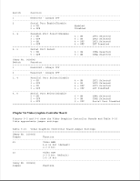
Serial/Parallel Interface Board Switch Settings
 |
View all HP Portable 386 manuals
Add to My Manuals
Save this manual to your list of manuals |
Page 156 highlights
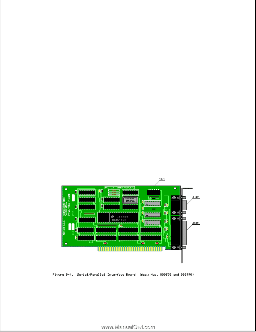
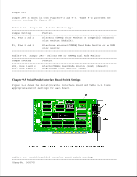
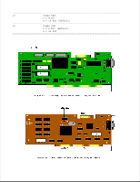
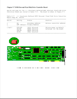
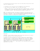
Jumper JP3 Jumper JP3 is shown in both Figures 9-2 and 9-3. Table 9-14 provides the correct setting for Jumper JP3. Table 9-13. Jumper P1 - Selects Monitor Type Jumper Setting Function P1, Pins 1 and 2 Selects a COMPAQ Color Monitor or compatible enhanced color monitor (default). P1, Pins 2 and 3 Selects an external COMPAQ Dual Mode Monitor or an RGB color monitor. Table 9-14. Jumper JP3 - Selects RGB or COMPAQ Dual Mode Monitor Jumper Setting Function JP3, Pins 1 and 2 Selects COMPAQ Dual Mode Monitor (3xxh) (default). JP3, Pins 2 and 3 Selects RGB color monitor. (2xxh) Chapter 9.5 Serial/Parallel Interface Board Switch Settings Figure 9-4 shows the Serial/Parallel Interface Board and Table 9-15 lists appropriate switch settings for each board. Table 9-15. Serial/Parallel Interface Board Switch Settings Assy No. 000570)
-
 1
1 -
2
-
3
-
4
-
5
-
6
-
7
-
8
-
9
-
10
-
11
-
12
-
13
-
14
-
15
-
16
-
17
-
18
-
19
-
20
-
21
-
22
-
23
-
24
-
25
-
26
-
27
-
28
-
29
-
30
-
31
-
32
-
33
-
34
-
35
-
36
-
37
-
38
-
39
-
40
-
41
-
42
-
43
-
44
-
45
-
46
-
47
-
48
-
49
-
50
-
51
-
52
-
53
-
54
-
55
-
56
-
57
-
58
-
59
-
60
-
61
-
62
-
63
-
64
-
65
-
66
-
67
-
68
-
69
-
70
-
71
-
72
-
73
-
74
-
75
-
76
-
77
-
78
-
79
-
80
-
81
-
82
-
83
-
84
-
85
-
86
-
87
-
88
-
89
-
90
-
91
-
92
-
93
-
94
-
95
-
96
-
97
-
98
-
99
-
100
-
101
-
102
-
103
-
104
-
105
-
106
-
107
-
108
-
109
-
110
-
111
-
112
-
113
-
114
-
115
-
116
-
117
-
118
-
119
-
120
-
121
-
122
-
123
-
124
-
125
-
126
-
127
-
128
-
129
-
130
-
131
-
132
-
133
-
134
-
135
-
136
-
137
-
138
-
139
-
140
-
141
-
142
-
143
-
144
-
145
-
146
-
147
-
148
-
149
-
150
-
 151
151 -
 152
152 -
 153
153 -
 154
154 -
 155
155 -
 156
156 -
 157
157 -
 158
158 -
 159
159 -
 160
160 -
 161
161 -
162
-
163
-
164
-
165
-
166
 |
 |