HP Portable 386 Compaq Portable 386 Personal Computer Maintenance and Service - Page 72
Interface Connector Cover, Locate the interface connector cover shown
 |
View all HP Portable 386 manuals
Add to My Manuals
Save this manual to your list of manuals |
Page 72 highlights
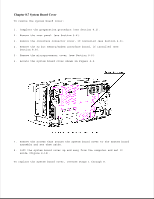
CAUTION Do not overtighten the screws Chapter 8.5 Interface Connector Cover The interface connector cover protects the 32 bit memory/modem interface connector when nothing is installed in the options compartment. This cover must be removed before either modem, the second serial interface board, or any of the memory expansion boards can be installed. To remove the interface connector cover: 1. Complete the preparation procedure (see Section 8.2). 2. Remove the rear panel (see Section 8.4). 3. Locate the interface connector cover shown in Figure 8-5. 4. Remove the three screws securing the interface connector cover and set them aside. 5. Remove the interface connector cover from the system board and set it
-
 1
1 -
2
-
3
-
4
-
5
-
6
-
7
-
8
-
9
-
10
-
11
-
12
-
13
-
14
-
15
-
16
-
17
-
18
-
19
-
20
-
21
-
22
-
23
-
24
-
25
-
26
-
27
-
28
-
29
-
30
-
31
-
32
-
33
-
34
-
35
-
36
-
37
-
38
-
39
-
40
-
41
-
42
-
43
-
44
-
45
-
46
-
47
-
48
-
49
-
50
-
51
-
52
-
53
-
54
-
55
-
56
-
57
-
58
-
59
-
60
-
61
-
62
-
63
-
64
-
65
-
66
-
 67
67 -
 68
68 -
 69
69 -
 70
70 -
 71
71 -
 72
72 -
 73
73 -
 74
74 -
 75
75 -
 76
76 -
 77
77 -
78
-
79
-
80
-
81
-
82
-
83
-
84
-
85
-
86
-
87
-
88
-
89
-
90
-
91
-
92
-
93
-
94
-
95
-
96
-
97
-
98
-
99
-
100
-
101
-
102
-
103
-
104
-
105
-
106
-
107
-
108
-
109
-
110
-
111
-
112
-
113
-
114
-
115
-
116
-
117
-
118
-
119
-
120
-
121
-
122
-
123
-
124
-
125
-
126
-
127
-
128
-
129
-
130
-
131
-
132
-
133
-
134
-
135
-
136
-
137
-
138
-
139
-
140
-
141
-
142
-
143
-
144
-
145
-
146
-
147
-
148
-
149
-
150
-
151
-
152
-
153
-
154
-
155
-
156
-
157
-
158
-
159
-
160
-
161
-
162
-
163
-
164
-
165
-
166
 |
 |

>>>>>>>>>>>>>>>>>>>>>>>>>>>>>>>>>>>>>>><<<<<<<<<<<<<<<<<<<<<<<<<<<<<<<<<<<<<<<
CAUTION
Do not overtighten the screws.
>>>>>>>>>>>>>>>>>>>>>>>>>>>>>>>>>>>>>>><<<<<<<<<<<<<<<<<<<<<<<<<<<<<<<<<<<<<<<
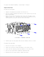
Chapter 8.5 Interface Connector Cover
The interface connector cover protects the 32 bit memory/modem interface
connector when nothing is installed in the options compartment. This cover
must be removed before either modem, the second serial interface board, or
any of the memory expansion boards can be installed.
To remove the interface connector cover:
1. Complete the preparation procedure (see Section 8.2).
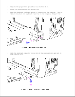
2. Remove the rear panel (see Section 8.4).
3. Locate the interface connector cover shown in Figure 8-5.
4. Remove the three screws securing the interface connector cover and set
them aside.
5. Remove the interface connector cover from the system board and set it