HP Portable 386 Compaq Portable 386 Personal Computer Maintenance and Service - Page 88
hole at one end of the module., Grasp the end of the module, pull up
 |
View all HP Portable 386 manuals
Add to My Manuals
Save this manual to your list of manuals |
Page 88 highlights
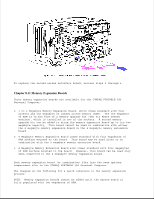
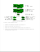
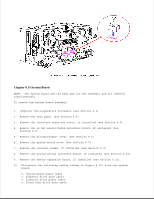
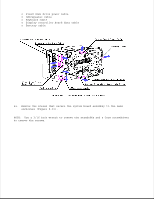
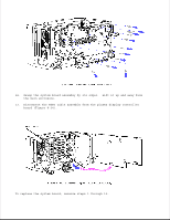
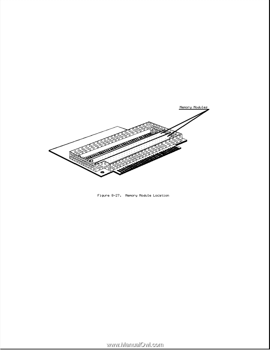
1. Complete the preparation procedure (see Section 8.2). 2. Remove the rear panel (see Section 8.4). 3. Remove the 32 bit memory/modem interface board (see Section 8.8). 4. Remove the 1 to 2 megabyte memory expansion board (see Section 8.11). 5. Locate the memory module that is to be replaced (Figure 8-27). 6. To release the module, insert a tool, such as a ball point pen, into the hole at one end of the module. 7. Grasp the end of the module, pull up, and "peel" it away from its socket (Figure 8-28).
-
 1
1 -
2
-
3
-
4
-
5
-
6
-
7
-
8
-
9
-
10
-
11
-
12
-
13
-
14
-
15
-
16
-
17
-
18
-
19
-
20
-
21
-
22
-
23
-
24
-
25
-
26
-
27
-
28
-
29
-
30
-
31
-
32
-
33
-
34
-
35
-
36
-
37
-
38
-
39
-
40
-
41
-
42
-
43
-
44
-
45
-
46
-
47
-
48
-
49
-
50
-
51
-
52
-
53
-
54
-
55
-
56
-
57
-
58
-
59
-
60
-
61
-
62
-
63
-
64
-
65
-
66
-
67
-
68
-
69
-
70
-
71
-
72
-
73
-
74
-
75
-
76
-
77
-
78
-
79
-
80
-
81
-
82
-
 83
83 -
 84
84 -
 85
85 -
 86
86 -
 87
87 -
 88
88 -
 89
89 -
 90
90 -
 91
91 -
 92
92 -
 93
93 -
94
-
95
-
96
-
97
-
98
-
99
-
100
-
101
-
102
-
103
-
104
-
105
-
106
-
107
-
108
-
109
-
110
-
111
-
112
-
113
-
114
-
115
-
116
-
117
-
118
-
119
-
120
-
121
-
122
-
123
-
124
-
125
-
126
-
127
-
128
-
129
-
130
-
131
-
132
-
133
-
134
-
135
-
136
-
137
-
138
-
139
-
140
-
141
-
142
-
143
-
144
-
145
-
146
-
147
-
148
-
149
-
150
-
151
-
152
-
153
-
154
-
155
-
156
-
157
-
158
-
159
-
160
-
161
-
162
-
163
-
164
-
165
-
166
 |
 |
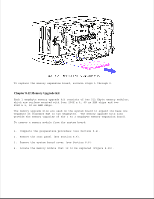
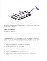
1. Complete the preparation procedure (see Section 8.2).
2. Remove the rear panel (see Section 8.4).
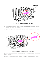
3. Remove the 32 bit memory/modem interface board (see Section 8.8).
4. Remove the 1 to 2 megabyte memory expansion board (see Section 8.11).
5. Locate the memory module that is to be replaced (Figure 8-27).
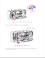
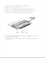
6. To release the module, insert a tool, such as a ball point pen, into the
hole at one end of the module.
7. Grasp the end of the module, pull up, and "peel" it away from its socket
(Figure 8-28).