HP Portable 386 Compaq Portable 386 Personal Computer Maintenance and Service - Page 109
LED/Speaker Cable, Keyboard Cable, and LED Assembly
 |
View all HP Portable 386 manuals
Add to My Manuals
Save this manual to your list of manuals |
Page 109 highlights
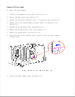
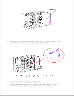
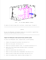
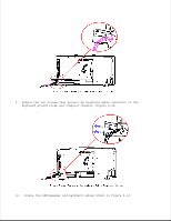
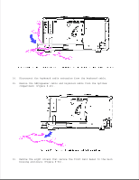
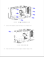
To replace the mass storage device enclosure, reverse steps 1 through 10 CAUTION Be sure the LED/speaker and keyboard cables are not pinched or exposed when replacing the mass storage devices enclosure Chapter 8.21 LED/Speaker Cable, Keyboard Cable, and LED Assembly To remove the LED/speaker cable, keyboard cable, and LED assembly: 1. Complete the preparation procedure (see Section 8.2). 2. Remove the rear panel (see Section 8.4). 3. Remove the interface connector cover, if installed (see Section 8.5). 4. Remove the 32 bit memory/modem interface board, if installed (see Section 8.8). 5. Remove the system board (see Section 8.14). 6. Remove the mass storage device subassembly (see Section 8.16). 7. Remove the mass storage device enclosure (see Section 8.20). 8. Locate the keyboard cable connector shown in Figure 8-59.
-
 1
1 -
2
-
3
-
4
-
5
-
6
-
7
-
8
-
9
-
10
-
11
-
12
-
13
-
14
-
15
-
16
-
17
-
18
-
19
-
20
-
21
-
22
-
23
-
24
-
25
-
26
-
27
-
28
-
29
-
30
-
31
-
32
-
33
-
34
-
35
-
36
-
37
-
38
-
39
-
40
-
41
-
42
-
43
-
44
-
45
-
46
-
47
-
48
-
49
-
50
-
51
-
52
-
53
-
54
-
55
-
56
-
57
-
58
-
59
-
60
-
61
-
62
-
63
-
64
-
65
-
66
-
67
-
68
-
69
-
70
-
71
-
72
-
73
-
74
-
75
-
76
-
77
-
78
-
79
-
80
-
81
-
82
-
83
-
84
-
85
-
86
-
87
-
88
-
89
-
90
-
91
-
92
-
93
-
94
-
95
-
96
-
97
-
98
-
99
-
100
-
101
-
102
-
103
-
 104
104 -
 105
105 -
 106
106 -
 107
107 -
 108
108 -
 109
109 -
 110
110 -
 111
111 -
 112
112 -
 113
113 -
 114
114 -
115
-
116
-
117
-
118
-
119
-
120
-
121
-
122
-
123
-
124
-
125
-
126
-
127
-
128
-
129
-
130
-
131
-
132
-
133
-
134
-
135
-
136
-
137
-
138
-
139
-
140
-
141
-
142
-
143
-
144
-
145
-
146
-
147
-
148
-
149
-
150
-
151
-
152
-
153
-
154
-
155
-
156
-
157
-
158
-
159
-
160
-
161
-
162
-
163
-
164
-
165
-
166
 |
 |
