HP Portable 386 Compaq Portable 386 Personal Computer Maintenance and Service - Page 131
Handle and Spreader Plate, Remove the mass storage device enclosure see
 |
View all HP Portable 386 manuals
Add to My Manuals
Save this manual to your list of manuals |
Page 131 highlights
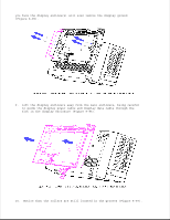
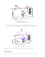
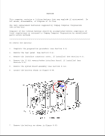
NOTE: For future replacement, notice the proper orientation of the display power cable assembly and the display data cable assembly. To replace the display data cable assembly, reverse steps 1 through 13. Chapter 8.27 Handle and Spreader Plate To remove the handle and spreader plate: 1. Complete the preparation procedure (see Section 8.2). 2. Remove the rear panel (see Section 8.4). 3. Remove the interface connector cover, if installed (see Section 8.5). 4. Remove the 32 bit memory/modem interface board, if installed (see Section 8.8). 5. Remove the system board assembly (see Section 8.14). 6. Remove the mass storage device subassembly (see Section 8.16). 7. Remove the mass storage device enclosure (see Section 8.20). NOTE: The handle can be removed at this point. To remove the handle and spreader plate, proceed with the following steps. 8. Remove the display enclosure (see Section 8.25). 9. Locate the plasma display hinges shown in Figure 8-94.
-
 1
1 -
2
-
3
-
4
-
5
-
6
-
7
-
8
-
9
-
10
-
11
-
12
-
13
-
14
-
15
-
16
-
17
-
18
-
19
-
20
-
21
-
22
-
23
-
24
-
25
-
26
-
27
-
28
-
29
-
30
-
31
-
32
-
33
-
34
-
35
-
36
-
37
-
38
-
39
-
40
-
41
-
42
-
43
-
44
-
45
-
46
-
47
-
48
-
49
-
50
-
51
-
52
-
53
-
54
-
55
-
56
-
57
-
58
-
59
-
60
-
61
-
62
-
63
-
64
-
65
-
66
-
67
-
68
-
69
-
70
-
71
-
72
-
73
-
74
-
75
-
76
-
77
-
78
-
79
-
80
-
81
-
82
-
83
-
84
-
85
-
86
-
87
-
88
-
89
-
90
-
91
-
92
-
93
-
94
-
95
-
96
-
97
-
98
-
99
-
100
-
101
-
102
-
103
-
104
-
105
-
106
-
107
-
108
-
109
-
110
-
111
-
112
-
113
-
114
-
115
-
116
-
117
-
118
-
119
-
120
-
121
-
122
-
123
-
124
-
125
-
 126
126 -
 127
127 -
 128
128 -
 129
129 -
 130
130 -
 131
131 -
 132
132 -
 133
133 -
 134
134 -
 135
135 -
 136
136 -
137
-
138
-
139
-
140
-
141
-
142
-
143
-
144
-
145
-
146
-
147
-
148
-
149
-
150
-
151
-
152
-
153
-
154
-
155
-
156
-
157
-
158
-
159
-
160
-
161
-
162
-
163
-
164
-
165
-
166
 |
 |
