HP Portable 386 Compaq Portable 386 Personal Computer Maintenance and Service - Page 91
System Board, Remove the memory expansion board, if installed see
 |
View all HP Portable 386 manuals
Add to My Manuals
Save this manual to your list of manuals |
Page 91 highlights
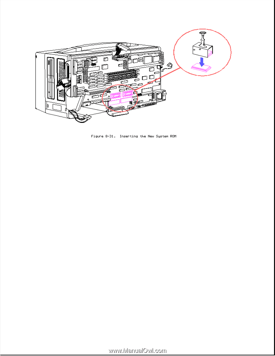
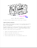
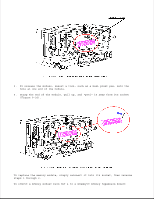
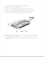
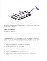
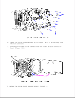
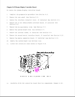
Chapter 8.14 System Board NOTE: The system board and the base pan are one assembly and are removed simultaneously. To remove the system board assembly: 1. Complete the preparation procedure (see Section 8.2). 2. Remove the rear panel (see Section 8.4). 3. Remove the interface connector cover, if installed (see Section 8.5). 4. Remove the 32 bit memory/modem interface board, if installed (see Section 8.8). 5. Remove the microprocessor cover (see Section 8.6). 6. Remove the system board cover (see Section 8.7). 7. Remove the internal modem, if installed (see Section 8.9). 8. Remove the second serial interface board, if installed (see Section 8.10). 9. Remove the memory expansion board, if installed (see Section 8.11). 10. Disconnect the following cables (shown in Figure 8-32) from the system board: o System board power cable o Diskette drive data cable o Diskette drive power cable o Fixed disk drive data cable
-
 1
1 -
2
-
3
-
4
-
5
-
6
-
7
-
8
-
9
-
10
-
11
-
12
-
13
-
14
-
15
-
16
-
17
-
18
-
19
-
20
-
21
-
22
-
23
-
24
-
25
-
26
-
27
-
28
-
29
-
30
-
31
-
32
-
33
-
34
-
35
-
36
-
37
-
38
-
39
-
40
-
41
-
42
-
43
-
44
-
45
-
46
-
47
-
48
-
49
-
50
-
51
-
52
-
53
-
54
-
55
-
56
-
57
-
58
-
59
-
60
-
61
-
62
-
63
-
64
-
65
-
66
-
67
-
68
-
69
-
70
-
71
-
72
-
73
-
74
-
75
-
76
-
77
-
78
-
79
-
80
-
81
-
82
-
83
-
84
-
85
-
 86
86 -
 87
87 -
 88
88 -
 89
89 -
 90
90 -
 91
91 -
 92
92 -
 93
93 -
 94
94 -
 95
95 -
 96
96 -
97
-
98
-
99
-
100
-
101
-
102
-
103
-
104
-
105
-
106
-
107
-
108
-
109
-
110
-
111
-
112
-
113
-
114
-
115
-
116
-
117
-
118
-
119
-
120
-
121
-
122
-
123
-
124
-
125
-
126
-
127
-
128
-
129
-
130
-
131
-
132
-
133
-
134
-
135
-
136
-
137
-
138
-
139
-
140
-
141
-
142
-
143
-
144
-
145
-
146
-
147
-
148
-
149
-
150
-
151
-
152
-
153
-
154
-
155
-
156
-
157
-
158
-
159
-
160
-
161
-
162
-
163
-
164
-
165
-
166
 |
 |