HP Xw4600 HP xw4600 Workstation - Service and Technical Reference Guide - Page 115
System board, Removing the system board
 |
UPC - 883585516483
View all HP Xw4600 manuals
Add to My Manuals
Save this manual to your list of manuals |
Page 115 highlights
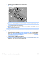
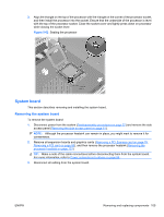
3. Align the triangle on the top of the processor with the triangle on the corner of the processor socket, and then install the processor into the socket. Ensure that the underside of the processor is level with the top of the processor socket. Close the socket cover and lightly press down on processor while closing the socket lever. Figure 5-62 Seating the processor System board This section describes removing and installing the system board. Removing the system board To remove the system board: 1. Disconnect power from the system (Predisassembly procedures on page 57) and remove the side access panel (Removing the side access panel on page 61). NOTE: Although the processor heatsink can remain in place, you might want to remove it for convenience. 2. Remove all expansion boards and graphics cards (Removing a PCI Express card on page 78, Removing a PCI card on page 80), and then remove the processor heatsink (Removing the processor heatsink on page 101). TIP: Make a note of the cable connections before disconnecting them from the system board. For more information, refer to Power connections to drives on page 86 . 3. Disconnect all cabling from the system board. ENWW Removing and replacing components 105
-
 1
1 -
2
-
3
-
4
-
5
-
6
-
7
-
8
-
9
-
10
-
11
-
12
-
13
-
14
-
15
-
16
-
17
-
18
-
19
-
20
-
21
-
22
-
23
-
24
-
25
-
26
-
27
-
28
-
29
-
30
-
31
-
32
-
33
-
34
-
35
-
36
-
37
-
38
-
39
-
40
-
41
-
42
-
43
-
44
-
45
-
46
-
47
-
48
-
49
-
50
-
51
-
52
-
53
-
54
-
55
-
56
-
57
-
58
-
59
-
60
-
61
-
62
-
63
-
64
-
65
-
66
-
67
-
68
-
69
-
70
-
71
-
72
-
73
-
74
-
75
-
76
-
77
-
78
-
79
-
80
-
81
-
82
-
83
-
84
-
85
-
86
-
87
-
88
-
89
-
90
-
91
-
92
-
93
-
94
-
95
-
96
-
97
-
98
-
99
-
100
-
101
-
102
-
103
-
104
-
105
-
106
-
107
-
108
-
109
-
 110
110 -
 111
111 -
 112
112 -
 113
113 -
 114
114 -
 115
115 -
 116
116 -
 117
117 -
 118
118 -
 119
119 -
 120
120 -
121
-
122
-
123
-
124
-
125
-
126
-
127
-
128
-
129
-
130
-
131
-
132
-
133
-
134
-
135
-
136
-
137
-
138
-
139
-
140
-
141
-
142
-
143
-
144
-
145
-
146
-
147
-
148
-
149
-
150
-
151
-
152
-
153
-
154
-
155
-
156
-
157
-
158
-
159
-
160
-
161
-
162
-
163
-
164
-
165
-
166
-
167
-
168
-
169
-
170
-
171
-
172
-
173
-
174
-
175
-
176
-
177
-
178
-
179
-
180
-
181
 |
 |
