HP Xw4600 HP xw4600 Workstation - Service and Technical Reference Guide - Page 93
Front PCI card guide and fan removal (optional), Removing the front PCI card guide and fan
 |
UPC - 883585516483
View all HP Xw4600 manuals
Add to My Manuals
Save this manual to your list of manuals |
Page 93 highlights
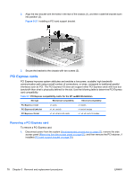
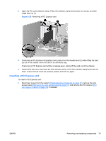
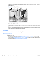
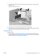
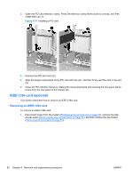
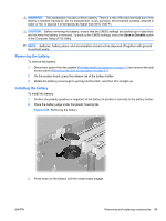
2. Open the PCI card retention clamp. Press the retention clamp levers down to unsnap, and then rotate them up (1). Figure 5-32 Removing an IEEE-1394 card 3. Disconnect the front I/O cable and power cable from the card (2). 4. Lift the IEEE-1394 card out of the chassis (3). Store the card in an anti static bag. 5. Install a PCI slot cover and close the PCI card retention clamp. If the PCI levers do not close, ensure that all cards are properly seated, and then try again. NOTE: To install an IEEE-1394 card, reverse the previous steps. Front PCI card guide and fan removal (optional) This unit acts as a front fan housing and card guide. This section describes how to remove and replace the fan housing/card guide and the front fan. NOTE: The fan is only used for special configurations, but the card guide is used with all full-length add-in cards. Removing the front PCI card guide and fan To remove the front PCI card guide and fan: 1. Disconnect power from the system (Predisassembly procedures on page 57), remove the side access panel (Removing the side access panel on page 61), and then remove the front bezel (Removing the front bezel on page 65). ENWW Removing and replacing components 83
-
 1
1 -
2
-
3
-
4
-
5
-
6
-
7
-
8
-
9
-
10
-
11
-
12
-
13
-
14
-
15
-
16
-
17
-
18
-
19
-
20
-
21
-
22
-
23
-
24
-
25
-
26
-
27
-
28
-
29
-
30
-
31
-
32
-
33
-
34
-
35
-
36
-
37
-
38
-
39
-
40
-
41
-
42
-
43
-
44
-
45
-
46
-
47
-
48
-
49
-
50
-
51
-
52
-
53
-
54
-
55
-
56
-
57
-
58
-
59
-
60
-
61
-
62
-
63
-
64
-
65
-
66
-
67
-
68
-
69
-
70
-
71
-
72
-
73
-
74
-
75
-
76
-
77
-
78
-
79
-
80
-
81
-
82
-
83
-
84
-
85
-
86
-
87
-
 88
88 -
 89
89 -
 90
90 -
 91
91 -
 92
92 -
 93
93 -
 94
94 -
 95
95 -
 96
96 -
 97
97 -
 98
98 -
99
-
100
-
101
-
102
-
103
-
104
-
105
-
106
-
107
-
108
-
109
-
110
-
111
-
112
-
113
-
114
-
115
-
116
-
117
-
118
-
119
-
120
-
121
-
122
-
123
-
124
-
125
-
126
-
127
-
128
-
129
-
130
-
131
-
132
-
133
-
134
-
135
-
136
-
137
-
138
-
139
-
140
-
141
-
142
-
143
-
144
-
145
-
146
-
147
-
148
-
149
-
150
-
151
-
152
-
153
-
154
-
155
-
156
-
157
-
158
-
159
-
160
-
161
-
162
-
163
-
164
-
165
-
166
-
167
-
168
-
169
-
170
-
171
-
172
-
173
-
174
-
175
-
176
-
177
-
178
-
179
-
180
-
181
 |
 |
