HP Xw4600 HP xw4600 Workstation - Service and Technical Reference Guide - Page 175
pin power auxiliary PCI Express, cable connector, Color, Signal, Workstation AUX_IN connector
 |
UPC - 883585516483
View all HP Xw4600 manuals
Add to My Manuals
Save this manual to your list of manuals |
Page 175 highlights
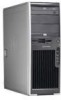
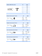
6-pin power (auxiliary PCI Express) cable connector Pin Color Signal 46 1 YEL +12 V-D 2 YEL +12 V-D 3 YEL +12 V-D 13 4 BLK 5 BLK 6 BLK GND GND GND CAUTION: Ensure that you can differentiate between which power cable connects to the PCI Express x16 graphics card and which power cable connects to the system board. These two cables have different pin counts and different colors. The PCI Express power cable has a 6-pin black connector, and the system board power cable has an 4-pin white connector. When power is present, you must never connect the PCI Express power cable to the system board. If you do so, the system board can be damaged and your warranty voided. To see a picture of the PCI Express cable and where it must be connected, see PCI Express cards on page 78. NOTE: The 6-pin power (auxiliary PCI Express) is only required with highpowered graphics cards. Workstation AUX_IN connector Pin Signal 1 AUX_LEFT 2 AGND 3 AGND 4 AUX_RIGHT Internal USB system board 2x5 connector Pin Signal 1 +5V 2 +5V 3 USB6# 4 USB7# ENWW Connector pin descriptions 165
-
 1
1 -
2
-
3
-
4
-
5
-
6
-
7
-
8
-
9
-
10
-
11
-
12
-
13
-
14
-
15
-
16
-
17
-
18
-
19
-
20
-
21
-
22
-
23
-
24
-
25
-
26
-
27
-
28
-
29
-
30
-
31
-
32
-
33
-
34
-
35
-
36
-
37
-
38
-
39
-
40
-
41
-
42
-
43
-
44
-
45
-
46
-
47
-
48
-
49
-
50
-
51
-
52
-
53
-
54
-
55
-
56
-
57
-
58
-
59
-
60
-
61
-
62
-
63
-
64
-
65
-
66
-
67
-
68
-
69
-
70
-
71
-
72
-
73
-
74
-
75
-
76
-
77
-
78
-
79
-
80
-
81
-
82
-
83
-
84
-
85
-
86
-
87
-
88
-
89
-
90
-
91
-
92
-
93
-
94
-
95
-
96
-
97
-
98
-
99
-
100
-
101
-
102
-
103
-
104
-
105
-
106
-
107
-
108
-
109
-
110
-
111
-
112
-
113
-
114
-
115
-
116
-
117
-
118
-
119
-
120
-
121
-
122
-
123
-
124
-
125
-
126
-
127
-
128
-
129
-
130
-
131
-
132
-
133
-
134
-
135
-
136
-
137
-
138
-
139
-
140
-
141
-
142
-
143
-
144
-
145
-
146
-
147
-
148
-
149
-
150
-
151
-
152
-
153
-
154
-
155
-
156
-
157
-
158
-
159
-
160
-
161
-
162
-
163
-
164
-
165
-
166
-
167
-
168
-
169
-
 170
170 -
 171
171 -
 172
172 -
 173
173 -
 174
174 -
 175
175 -
 176
176 -
 177
177 -
 178
178 -
 179
179 -
 180
180 -
181
 |
 |
