HP Xw4600 HP xw4600 Workstation - Service and Technical Reference Guide - Page 98
Removing an optical drive (minitower configuration),
 |
UPC - 883585516483
View all HP Xw4600 manuals
Add to My Manuals
Save this manual to your list of manuals |
Page 98 highlights
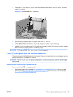
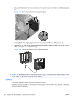
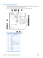
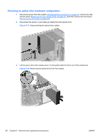
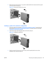
Removing an optical drive (minitower configuration) 1. Disconnect power from the system (Predisassembly procedures on page 57), remove the side access panel (Removing the side access panel on page 61), and then remove the front bezel (Removing the front bezel on page 65). 2. Disconnect the power (1) and data (2) cables from the optical drive. Figure 5-37 Disconnecting the optical drive cables 3. Lift the green drive-lock release lever (1) and gently slide the drive out of the chassis (2). Figure 5-38 Removing the optical drive from the chassis 88 Chapter 5 Removal and replacement procedures ENWW
-
 1
1 -
2
-
3
-
4
-
5
-
6
-
7
-
8
-
9
-
10
-
11
-
12
-
13
-
14
-
15
-
16
-
17
-
18
-
19
-
20
-
21
-
22
-
23
-
24
-
25
-
26
-
27
-
28
-
29
-
30
-
31
-
32
-
33
-
34
-
35
-
36
-
37
-
38
-
39
-
40
-
41
-
42
-
43
-
44
-
45
-
46
-
47
-
48
-
49
-
50
-
51
-
52
-
53
-
54
-
55
-
56
-
57
-
58
-
59
-
60
-
61
-
62
-
63
-
64
-
65
-
66
-
67
-
68
-
69
-
70
-
71
-
72
-
73
-
74
-
75
-
76
-
77
-
78
-
79
-
80
-
81
-
82
-
83
-
84
-
85
-
86
-
87
-
88
-
89
-
90
-
91
-
92
-
 93
93 -
 94
94 -
 95
95 -
 96
96 -
 97
97 -
 98
98 -
 99
99 -
 100
100 -
 101
101 -
 102
102 -
 103
103 -
104
-
105
-
106
-
107
-
108
-
109
-
110
-
111
-
112
-
113
-
114
-
115
-
116
-
117
-
118
-
119
-
120
-
121
-
122
-
123
-
124
-
125
-
126
-
127
-
128
-
129
-
130
-
131
-
132
-
133
-
134
-
135
-
136
-
137
-
138
-
139
-
140
-
141
-
142
-
143
-
144
-
145
-
146
-
147
-
148
-
149
-
150
-
151
-
152
-
153
-
154
-
155
-
156
-
157
-
158
-
159
-
160
-
161
-
162
-
163
-
164
-
165
-
166
-
167
-
168
-
169
-
170
-
171
-
172
-
173
-
174
-
175
-
176
-
177
-
178
-
179
-
180
-
181
 |
 |

Removing an optical drive (minitower configuration)
1.
Disconnect power from the system (
Predisassembly procedures
on page
57
), remove the side
access panel (
Removing the side access panel
on page
61
), and then remove the front bezel
(
Removing the front bezel
on page
65
).
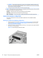
2.
Disconnect the power (1) and data (2) cables from the optical drive.
Figure 5-37
Disconnecting the optical drive cables
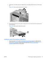
3.
Lift the green drive-lock release lever (1) and gently slide the drive out of the chassis (2).
Figure 5-38
Removing the optical drive from the chassis
88
Chapter 5
Removal and replacement procedures
ENWW