HP Xw4600 HP xw4600 Workstation - Service and Technical Reference Guide - Page 77
Installing the front panel I/O device assembly,
 |
UPC - 883585516483
View all HP Xw4600 manuals
Add to My Manuals
Save this manual to your list of manuals |
Page 77 highlights
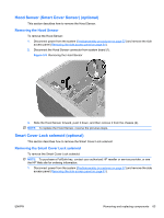
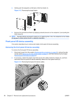
3. Remove the two smaller Torx screws (1) that hold the front panel I/O device assembly and bracket to the chassis (3). Figure 5-14 Removing the front panel I/O device assembly 4. Remove the two larger Torx screws (2) that hold the front panel I/O device assembly to the bracket (3). 5. Separate the bracket from the front panel I/O device assembly. 6. Pull the front panel I/O device assembly out about two inches from the chassis (5). 7. Pull the front panel cables through the chassis and through the front of the workstation. You might have to slide the cables out one at a time. Installing the front panel I/O device assembly To instal the front panel I/O device assembly: 1. Thread each front panel I/O device assembly cable through the same holes from which they were removed. 2. Push the front panel I/O device assembly into the chassis. Using your fingers, orient the cables so that there is enough room for the front panel I/O device assembly to easily fit in its slot. 3. Loosely place the bracket on the front panel I/O device assembly and hook the bracket to the chassis. ENWW Removing and replacing components 67
-
 1
1 -
2
-
3
-
4
-
5
-
6
-
7
-
8
-
9
-
10
-
11
-
12
-
13
-
14
-
15
-
16
-
17
-
18
-
19
-
20
-
21
-
22
-
23
-
24
-
25
-
26
-
27
-
28
-
29
-
30
-
31
-
32
-
33
-
34
-
35
-
36
-
37
-
38
-
39
-
40
-
41
-
42
-
43
-
44
-
45
-
46
-
47
-
48
-
49
-
50
-
51
-
52
-
53
-
54
-
55
-
56
-
57
-
58
-
59
-
60
-
61
-
62
-
63
-
64
-
65
-
66
-
67
-
68
-
69
-
70
-
71
-
 72
72 -
 73
73 -
 74
74 -
 75
75 -
 76
76 -
 77
77 -
 78
78 -
 79
79 -
 80
80 -
 81
81 -
 82
82 -
83
-
84
-
85
-
86
-
87
-
88
-
89
-
90
-
91
-
92
-
93
-
94
-
95
-
96
-
97
-
98
-
99
-
100
-
101
-
102
-
103
-
104
-
105
-
106
-
107
-
108
-
109
-
110
-
111
-
112
-
113
-
114
-
115
-
116
-
117
-
118
-
119
-
120
-
121
-
122
-
123
-
124
-
125
-
126
-
127
-
128
-
129
-
130
-
131
-
132
-
133
-
134
-
135
-
136
-
137
-
138
-
139
-
140
-
141
-
142
-
143
-
144
-
145
-
146
-
147
-
148
-
149
-
150
-
151
-
152
-
153
-
154
-
155
-
156
-
157
-
158
-
159
-
160
-
161
-
162
-
163
-
164
-
165
-
166
-
167
-
168
-
169
-
170
-
171
-
172
-
173
-
174
-
175
-
176
-
177
-
178
-
179
-
180
-
181
 |
 |
