HP Xw4600 HP xw4600 Workstation - Service and Technical Reference Guide - Page 78
Power button assembly, Removing the power button assembly
 |
UPC - 883585516483
View all HP Xw4600 manuals
Add to My Manuals
Save this manual to your list of manuals |
Page 78 highlights
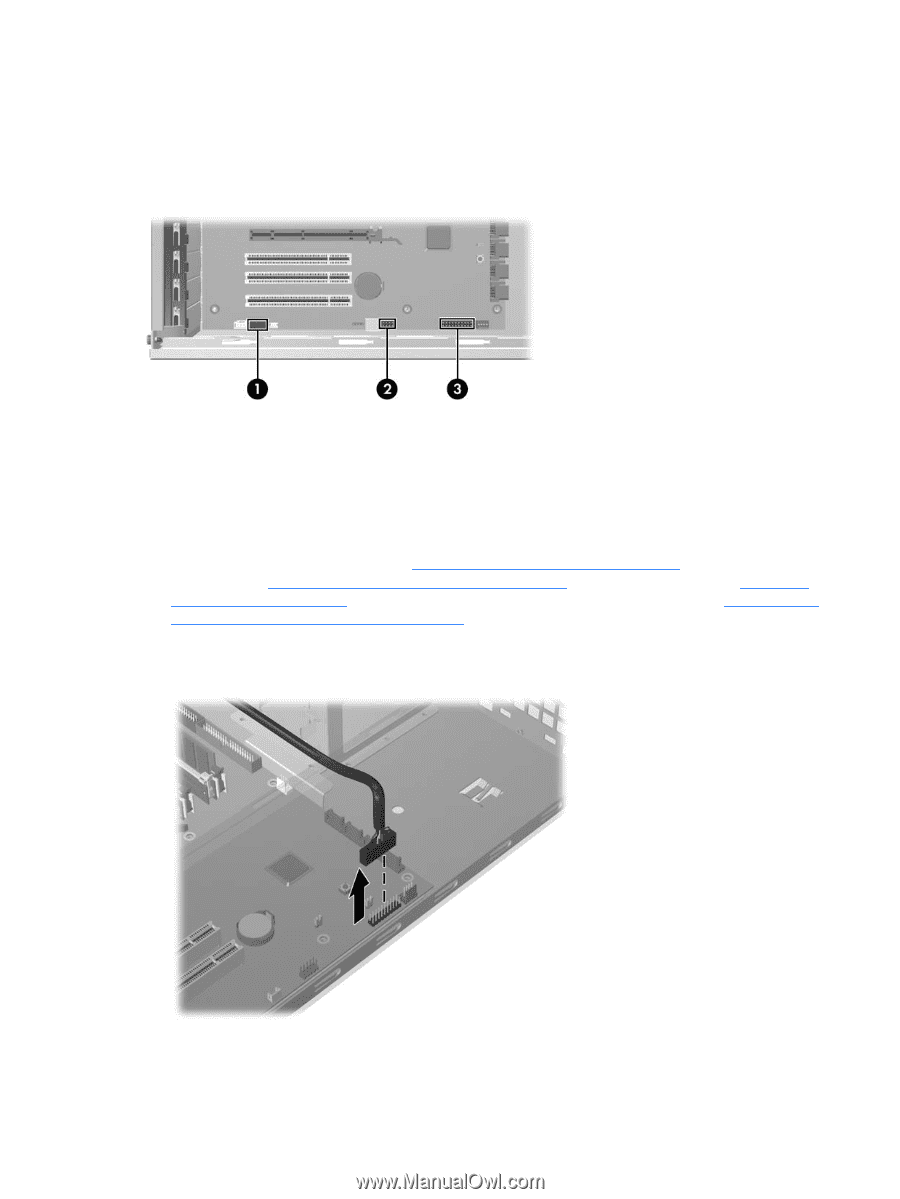
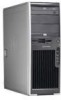
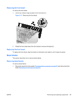
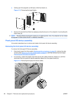
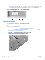
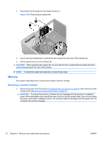
4. Screw the bracket to the front panel I/O device assembly, and then screw the bracket to the chassis. 5. Connect the front audio cable to the audio connector (1). Connect the front USB cable to the USB connector (2). Connect the front control panel cable to the control panel connector (3). If an IEEE-1394 card is installed, connect the front IEEE-1394 cable to the card connector. Figure 5-15 Attaching the front panel I/O device assembly cables Power button assembly This section describes how to remove the power button assembly. Removing the power button assembly To remove the power button assembly: 1. Disconnect power from the system (Predisassembly procedures on page 57), remove the side access panel (Removing the side access panel on page 61), remove the front bezel (Removing the front bezel on page 65), and then remove the front panel I/O device assembly (Removing the front panel I/O device assembly on page 66). 2. Disconnect the power button assembly cable from the system board. Figure 5-16 Removing the power button assembly cable 68 Chapter 5 Removal and replacement procedures ENWW
-
 1
1 -
2
-
3
-
4
-
5
-
6
-
7
-
8
-
9
-
10
-
11
-
12
-
13
-
14
-
15
-
16
-
17
-
18
-
19
-
20
-
21
-
22
-
23
-
24
-
25
-
26
-
27
-
28
-
29
-
30
-
31
-
32
-
33
-
34
-
35
-
36
-
37
-
38
-
39
-
40
-
41
-
42
-
43
-
44
-
45
-
46
-
47
-
48
-
49
-
50
-
51
-
52
-
53
-
54
-
55
-
56
-
57
-
58
-
59
-
60
-
61
-
62
-
63
-
64
-
65
-
66
-
67
-
68
-
69
-
70
-
71
-
72
-
 73
73 -
 74
74 -
 75
75 -
 76
76 -
 77
77 -
 78
78 -
 79
79 -
 80
80 -
 81
81 -
 82
82 -
 83
83 -
84
-
85
-
86
-
87
-
88
-
89
-
90
-
91
-
92
-
93
-
94
-
95
-
96
-
97
-
98
-
99
-
100
-
101
-
102
-
103
-
104
-
105
-
106
-
107
-
108
-
109
-
110
-
111
-
112
-
113
-
114
-
115
-
116
-
117
-
118
-
119
-
120
-
121
-
122
-
123
-
124
-
125
-
126
-
127
-
128
-
129
-
130
-
131
-
132
-
133
-
134
-
135
-
136
-
137
-
138
-
139
-
140
-
141
-
142
-
143
-
144
-
145
-
146
-
147
-
148
-
149
-
150
-
151
-
152
-
153
-
154
-
155
-
156
-
157
-
158
-
159
-
160
-
161
-
162
-
163
-
164
-
165
-
166
-
167
-
168
-
169
-
170
-
171
-
172
-
173
-
174
-
175
-
176
-
177
-
178
-
179
-
180
-
181
 |
 |