HP Xw4600 HP xw4600 Workstation - Service and Technical Reference Guide - Page 99
Installing an optical drive (minitower configuration),
 |
UPC - 883585516483
View all HP Xw4600 manuals
Add to My Manuals
Save this manual to your list of manuals |
Page 99 highlights
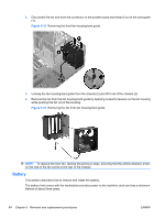
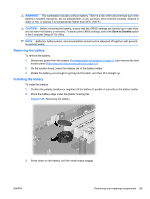
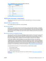
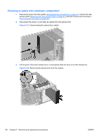
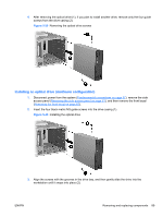
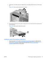
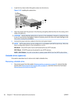
4. After removing the optical drive (1), if you plan to install another drive, remove only the four guide screws from the drive casing (2). Figure 5-39 Removing the optical drive screws Installing an optical drive (minitower configuration) 1. Disconnect power from the system (Predisassembly procedures on page 57), remove the side access panel (Removing the side access panel on page 61), and then remove the front bezel (Removing the front bezel on page 65). 2. Insert the four black metric M3 guide screws into the drive casing (1). Figure 5-40 Installing the optical drive 3. Align the screws with the grooves in the drive bay, and then gently slide the drive into the workstation until it snaps into place (2). ENWW Removing and replacing components 89
-
 1
1 -
2
-
3
-
4
-
5
-
6
-
7
-
8
-
9
-
10
-
11
-
12
-
13
-
14
-
15
-
16
-
17
-
18
-
19
-
20
-
21
-
22
-
23
-
24
-
25
-
26
-
27
-
28
-
29
-
30
-
31
-
32
-
33
-
34
-
35
-
36
-
37
-
38
-
39
-
40
-
41
-
42
-
43
-
44
-
45
-
46
-
47
-
48
-
49
-
50
-
51
-
52
-
53
-
54
-
55
-
56
-
57
-
58
-
59
-
60
-
61
-
62
-
63
-
64
-
65
-
66
-
67
-
68
-
69
-
70
-
71
-
72
-
73
-
74
-
75
-
76
-
77
-
78
-
79
-
80
-
81
-
82
-
83
-
84
-
85
-
86
-
87
-
88
-
89
-
90
-
91
-
92
-
93
-
 94
94 -
 95
95 -
 96
96 -
 97
97 -
 98
98 -
 99
99 -
 100
100 -
 101
101 -
 102
102 -
 103
103 -
 104
104 -
105
-
106
-
107
-
108
-
109
-
110
-
111
-
112
-
113
-
114
-
115
-
116
-
117
-
118
-
119
-
120
-
121
-
122
-
123
-
124
-
125
-
126
-
127
-
128
-
129
-
130
-
131
-
132
-
133
-
134
-
135
-
136
-
137
-
138
-
139
-
140
-
141
-
142
-
143
-
144
-
145
-
146
-
147
-
148
-
149
-
150
-
151
-
152
-
153
-
154
-
155
-
156
-
157
-
158
-
159
-
160
-
161
-
162
-
163
-
164
-
165
-
166
-
167
-
168
-
169
-
170
-
171
-
172
-
173
-
174
-
175
-
176
-
177
-
178
-
179
-
180
-
181
 |
 |
