HP Xw4600 HP xw4600 Workstation - Service and Technical Reference Guide - Page 82
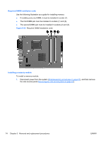
Memory, Removing a memory module
 |
UPC - 883585516483
View all HP Xw4600 manuals
Add to My Manuals
Save this manual to your list of manuals |
Page 82 highlights
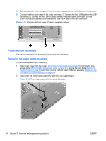
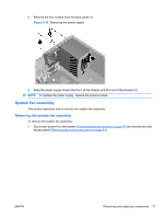
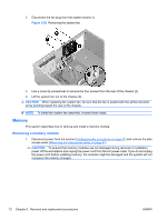
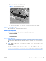
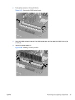
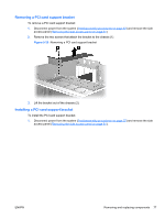
2. Disconnect the fan plug from the system board (1). Figure 5-20 Removing the system fan 3. Use a cross-tip screwdriver to remove the four screws from the rear of the chassis (2). 4. Lift the system fan out of the chassis (3). CAUTION: When replacing the system fan, be sure that the fan is seated with the airflow direction arrow pointing toward the rear of the chassis. NOTE: To install the system fan assembly, reverse these steps. Memory This section describes how to remove and install a memory module. Removing a memory module 1. Disconnect power from the system (Predisassembly procedures on page 57) and remove the side access panel (Removing the side access panel on page 61). CAUTION: To ensure that memory modules are not damaged during removal or installation, power off the workstation and unplug the power cord from the AC power outlet. If you do not unplug the power cord before installing memory, the modules might be damaged and the system will not recognize the memory changes. 72 Chapter 5 Removal and replacement procedures ENWW
-
 1
1 -
2
-
3
-
4
-
5
-
6
-
7
-
8
-
9
-
10
-
11
-
12
-
13
-
14
-
15
-
16
-
17
-
18
-
19
-
20
-
21
-
22
-
23
-
24
-
25
-
26
-
27
-
28
-
29
-
30
-
31
-
32
-
33
-
34
-
35
-
36
-
37
-
38
-
39
-
40
-
41
-
42
-
43
-
44
-
45
-
46
-
47
-
48
-
49
-
50
-
51
-
52
-
53
-
54
-
55
-
56
-
57
-
58
-
59
-
60
-
61
-
62
-
63
-
64
-
65
-
66
-
67
-
68
-
69
-
70
-
71
-
72
-
73
-
74
-
75
-
76
-
 77
77 -
 78
78 -
 79
79 -
 80
80 -
 81
81 -
 82
82 -
 83
83 -
 84
84 -
 85
85 -
 86
86 -
 87
87 -
88
-
89
-
90
-
91
-
92
-
93
-
94
-
95
-
96
-
97
-
98
-
99
-
100
-
101
-
102
-
103
-
104
-
105
-
106
-
107
-
108
-
109
-
110
-
111
-
112
-
113
-
114
-
115
-
116
-
117
-
118
-
119
-
120
-
121
-
122
-
123
-
124
-
125
-
126
-
127
-
128
-
129
-
130
-
131
-
132
-
133
-
134
-
135
-
136
-
137
-
138
-
139
-
140
-
141
-
142
-
143
-
144
-
145
-
146
-
147
-
148
-
149
-
150
-
151
-
152
-
153
-
154
-
155
-
156
-
157
-
158
-
159
-
160
-
161
-
162
-
163
-
164
-
165
-
166
-
167
-
168
-
169
-
170
-
171
-
172
-
173
-
174
-
175
-
176
-
177
-
178
-
179
-
180
-
181
 |
 |
