HP Xw4600 HP xw4600 Workstation - Service and Technical Reference Guide - Page 76
Front panel I/O device assembly
 |
UPC - 883585516483
View all HP Xw4600 manuals
Add to My Manuals
Save this manual to your list of manuals |
Page 76 highlights
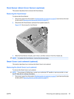
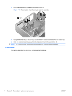
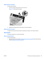
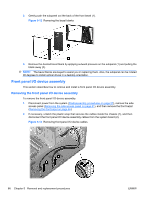
2. Gently push the subpanel out the back of the front bezel (1). Figure 5-12 Removing the bezel blanks 3. Remove the desired bezel blank by applying outward pressure on the subpanel (1) and pulling the blank away (2). NOTE: The bezel blanks are keyed to assist you in replacing them. Also, the subpanel can be rotated 90 degrees to install optical drives in a desktop orientation. Front panel I/O device assembly This section describes how to remove and install a front panel I/O device assembly. Removing the front panel I/O device assembly To remove the front panel I/O device assembly: 1. Disconnect power from the system (Predisassembly procedures on page 57), remove the side access panel (Removing the side access panel on page 61), and then remove the front bezel (Removing the front bezel on page 65). 2. If necessary, unlatch the plastic snap that secures the cables inside the chassis (1), and then disconnect the front panel I/O device assembly cables from the system board (2). Figure 5-13 Removing front panel I/O device cables 66 Chapter 5 Removal and replacement procedures ENWW
-
 1
1 -
2
-
3
-
4
-
5
-
6
-
7
-
8
-
9
-
10
-
11
-
12
-
13
-
14
-
15
-
16
-
17
-
18
-
19
-
20
-
21
-
22
-
23
-
24
-
25
-
26
-
27
-
28
-
29
-
30
-
31
-
32
-
33
-
34
-
35
-
36
-
37
-
38
-
39
-
40
-
41
-
42
-
43
-
44
-
45
-
46
-
47
-
48
-
49
-
50
-
51
-
52
-
53
-
54
-
55
-
56
-
57
-
58
-
59
-
60
-
61
-
62
-
63
-
64
-
65
-
66
-
67
-
68
-
69
-
70
-
 71
71 -
 72
72 -
 73
73 -
 74
74 -
 75
75 -
 76
76 -
 77
77 -
 78
78 -
 79
79 -
 80
80 -
 81
81 -
82
-
83
-
84
-
85
-
86
-
87
-
88
-
89
-
90
-
91
-
92
-
93
-
94
-
95
-
96
-
97
-
98
-
99
-
100
-
101
-
102
-
103
-
104
-
105
-
106
-
107
-
108
-
109
-
110
-
111
-
112
-
113
-
114
-
115
-
116
-
117
-
118
-
119
-
120
-
121
-
122
-
123
-
124
-
125
-
126
-
127
-
128
-
129
-
130
-
131
-
132
-
133
-
134
-
135
-
136
-
137
-
138
-
139
-
140
-
141
-
142
-
143
-
144
-
145
-
146
-
147
-
148
-
149
-
150
-
151
-
152
-
153
-
154
-
155
-
156
-
157
-
158
-
159
-
160
-
161
-
162
-
163
-
164
-
165
-
166
-
167
-
168
-
169
-
170
-
171
-
172
-
173
-
174
-
175
-
176
-
177
-
178
-
179
-
180
-
181
 |
 |
