JVC DVP9 Instruction Manual - Page 52
Dubbing From A Video Unit Equipped With A DV OUT Connector (Digital Dubbing), DUBBING cont.
 |
UPC - 046838161100
View all JVC DVP9 manuals
Add to My Manuals
Save this manual to your list of manuals |
Page 52 highlights
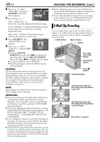
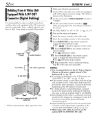
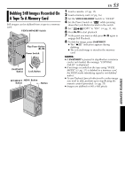
52 EN Dubbing From A Video Unit Equipped With A DV OUT Connector (Digital Dubbing) It is also possible to copy recorded scenes from another video unit equipped with a DV connector onto the camcorder. Since a digital signal is sent, there is little if any image or sound deterioration. Connector Cover* To DV IN/OUT Core filter DV cable (optional) To DV OUT Video unit equipped with DV connector * When connecting the cable, open the cover. DUBBING (cont.) 1 Make sure all units are turned off. 2 Connect this camcorder to a video unit equipped with a DV output connector using a DV cable as shown in the illustration. 3 Set this camcorder's VIDEO/MEMORY Switch to "VIDEO". 4 Set this camcorder's Power Switch to "P" while pressing down the Lock Button located on the switch. 5 Set "REC MODE" to "SP" or "LP". (੬ pg. 31, 34) 6 Turn on the video unit's power. 7 Insert the source cassette in the video unit. 8 Insert the recording cassette in this camcorder. 9 Press START/STOP on the remote control to engage the Record-Pause mode. ● The " DV. IN " indication appears on the screen. 10 Press START/STOP on the remote control to start recording. ● The indication rotates. 11 Press START/STOP on the remote control again to engage the Record-Pause mode. ● The indication stops rotating. 12 Repeat steps 10 - 11 for additional editing. Stop the video unit and camcorder. NOTES: ● It is recommended to use the AC Power Adapter/ Charger as the power supply instead of the battery pack. (੬ pg. 11) ● If no image is displayed on the LCD monitor, set "S/AV INPUT" to "OFF". (੬ pg. 31, 40) ● If the remote control is used when both the player and recorder are JVC video units, both units will perform the same operation. To prevent this from happening, press the buttons on both units. ● If a blank portion or disturbed image is played back on the player during dubbing, the dubbing may stop so that an unusual image is not dubbed. ● Even though the DV cable is connected correctly, sometimes the image may not appear in step 9. If this occurs, turn off the power and make connections again. ● Digital Dubbing is performed in the sound mode recorded on the original tape, regardless of the current "SOUND MODE" setting. (੬ pg. 34) ● When using a DV cable, be sure to use the optional JVC VC-VDV204U DV cable.
-
 1
1 -
2
-
3
-
4
-
5
-
6
-
7
-
8
-
9
-
10
-
11
-
12
-
13
-
14
-
15
-
16
-
17
-
18
-
19
-
20
-
21
-
22
-
23
-
24
-
25
-
26
-
27
-
28
-
29
-
30
-
31
-
32
-
33
-
34
-
35
-
36
-
37
-
38
-
39
-
40
-
41
-
42
-
43
-
44
-
45
-
46
-
 47
47 -
 48
48 -
 49
49 -
 50
50 -
 51
51 -
 52
52 -
 53
53 -
 54
54 -
 55
55 -
 56
56 -
 57
57 -
58
-
59
-
60
-
61
-
62
-
63
-
64
-
65
-
66
-
67
-
68
-
69
-
70
-
71
-
72
-
73
-
74
-
75
-
76
-
77
-
78
-
79
-
80
-
81
-
82
-
83
-
84
-
85
-
86
-
87
-
88
-
89
-
90
-
91
-
92
-
93
-
94
-
95
-
96
-
97
-
98
-
99
-
100
-
101
-
102
-
103
-
104
-
105
-
106
-
107
-
108
-
109
-
110
-
111
-
112
-
113
-
114
-
115
-
116
-
117
-
118
-
119
-
120
-
121
-
122
-
123
-
124
-
125
-
126
-
127
-
128
-
129
-
130
-
131
-
132
-
133
-
134
-
135
-
136
-
137
-
138
-
139
-
140
-
141
-
142
-
143
-
144
-
145
-
146
-
147
-
148
-
149
-
150
 |
 |