JVC DVP9 Instruction Manual - Page 77

Controls, Connectors, Indicators, Other Parts

Page 77 highlights

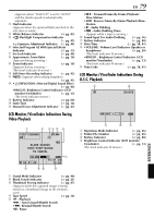
Controls a •E-Mail Clip Recording Button [E-MAIL pg. 49 •Information Button [INFO pg. 26 b Menu Button [MENU pg. 31 c •+, - Button pg. 31 •LCD Monitor Brightness Control [MONITOR BRIGHT pg. 13 d •Power Zoom Ring [T/W pg. 18 •Shuttle Search Ring [SHUTTLE SEARCH, 3/5 pg. 20 e •Recording Start/Stop Button pg. 17 •Play/Pause Button [4/9 pg. 20 f Power Switch [A, M, P, OFF pg. 13 g Lock Button pg. 13 h Snapshot Button [SNAPSHOT pg. 23, 41 i •Stop Button [8 pg. 20 •Digital Sound Button [D.SOUND]..... ੬ pg. 46 j •Index Button [INDEX pg. 26, 46, 56 •Navigation Button [NAVI pg. 47 k Set/Select Button [SET/SELECT pg. 31 l Battery Release Switch [BATT.RELEASE pg. 11 m Cassette Open/Eject Switch [OPEN/EJECT pg. 15 n Thumbnail Storing Button [NAVI STORE pg. 47 o VIDEO/MEMORY Switch [VIDEO/MEMORY pg. 13 p •Focus Adjustment Button [FOCUS] ... ੬ pg. 43 •Speaker Volume Control [VOL pg. 20 q •Backlight Compensation Button [BACK LIGHT pg. 45 •Speaker Volume Control [VOL pg. 20 r Dioptre Adjustment Control pg. 12 Connectors The connectors are located beneath the covers. S Digital Video Connector [DV IN/OUT] (i.Link pg. 51, 52, 62 * i.Link refers to the IEEE1394-1995 industry specification and extensions thereof. The logo is used for products compliant with the i.Link standard. T USB (Universal Serial Bus) Connector pg. 62 U S/AV connector pg. 22, 50, 59 V Headphone Connector pg. 56 No sound is output from the speaker when headphones are connected to this connector. EN 77 Indicators A Power Lamp pg. 13, 17 B Tally Lamp pg. 17, 37 Other Parts Y LCD Monitor pg. 12, 18 a Battery Pack Mount pg. 11 b Speaker pg. 20 c Grip Belt/Strap Eyelet pg. 6 d Viewfinder pg. 12 e Viewfinder Cleaning Hatch pg. 73 f Cassette Holder Cover pg. 15 g Camera Sensor Be careful not to cover this area, a sensor necessary for shooting is built-in here. h Stereo Microphone pg. 56 i Info-Shoe Attach only the optional JVC VL-V3U Video Light, VL-F3U Flash, MZ-V3U Stereo Zoom Microphone or MZ-V5U Stereo Microphone. Make sure to turn off the power of the camcorder and the video light, flash or microphone before attaching and removing them. j Lens k Lens Cover pg. 17 l Grip Belt Eyelet pg. 6 m Remote Sensor pg. 54 n Tripod Mounting Socket pg. 12 o Card Cover [MEMORY CARD pg. 16 REFERENCES

  • 1
  • 2
  • 3
  • 4
  • 5
  • 6
  • 7
  • 8
  • 9
  • 10
  • 11
  • 12
  • 13
  • 14
  • 15
  • 16
  • 17
  • 18
  • 19
  • 20
  • 21
  • 22
  • 23
  • 24
  • 25
  • 26
  • 27
  • 28
  • 29
  • 30
  • 31
  • 32
  • 33
  • 34
  • 35
  • 36
  • 37
  • 38
  • 39
  • 40
  • 41
  • 42
  • 43
  • 44
  • 45
  • 46
  • 47
  • 48
  • 49
  • 50
  • 51
  • 52
  • 53
  • 54
  • 55
  • 56
  • 57
  • 58
  • 59
  • 60
  • 61
  • 62
  • 63
  • 64
  • 65
  • 66
  • 67
  • 68
  • 69
  • 70
  • 71
  • 72
  • 73
  • 74
  • 75
  • 76
  • 77
  • 78
  • 79
  • 80
  • 81
  • 82
  • 83
  • 84
  • 85
  • 86
  • 87
  • 88
  • 89
  • 90
  • 91
  • 92
  • 93
  • 94
  • 95
  • 96
  • 97
  • 98
  • 99
  • 100
  • 101
  • 102
  • 103
  • 104
  • 105
  • 106
  • 107
  • 108
  • 109
  • 110
  • 111
  • 112
  • 113
  • 114
  • 115
  • 116
  • 117
  • 118
  • 119
  • 120
  • 121
  • 122
  • 123
  • 124
  • 125
  • 126
  • 127
  • 128
  • 129
  • 130
  • 131
  • 132
  • 133
  • 134
  • 135
  • 136
  • 137
  • 138
  • 139
  • 140
  • 141
  • 142
  • 143
  • 144
  • 145
  • 146
  • 147
  • 148
  • 149
  • 150

EN
77
Controls
a
•E-Mail Clip Recording Button
[E-MAIL]
............................................
±
pg. 49
•Information Button [INFO]
................
±
pg. 26
b
Menu Button [MENU]
..........................
±
pg. 31
c
•+, – Button
........................................
±
pg. 31
•LCD Monitor Brightness Control
[MONITOR BRIGHT +, –]
.................
±
pg. 13
d
•Power Zoom Ring [T/W]
....................
±
pg. 18
•Shuttle Search Ring
[SHUTTLE SEARCH,
3
/
5
]
........
±
pg. 20
e
•Recording Start/Stop Button
..............
±
pg. 17
•Play/Pause Button [
4
/
9
]
..................
±
pg. 20
f
Power Switch [
A
,
M
,
P
, OFF]
..........
±
pg. 13
g
Lock Button
.........................................
±
pg. 13
h
Snapshot Button [SNAPSHOT]
.......
±
pg. 23, 41
i
•Stop Button [
8
]
.................................
±
pg. 20
•Digital Sound Button [D.SOUND]
.....
±
pg. 46
j
•Index Button [INDEX]
...........
±
pg. 26, 46, 56
•Navigation Button [NAVI]
.................
±
pg. 47
k
Set/Select Button [SET/SELECT]
...........
±
pg. 31
l
Battery Release Switch
[BATT.RELEASE]
...................................
±
pg. 11
m
Cassette Open/Eject Switch
[OPEN/EJECT]
......................................
±
pg. 15
n
Thumbnail Storing Button
[NAVI STORE]
......................................
±
pg. 47
o
VIDEO/MEMORY Switch
[VIDEO/MEMORY]
..............................
±
pg. 13
p
•Focus Adjustment Button [FOCUS] ...
±
pg. 43
•Speaker Volume Control [VOL. +]
.....
±
pg. 20
q
•Backlight Compensation Button
[BACK LIGHT]
...................................
±
pg. 45
•Speaker Volume Control
[VOL. –]
............................................
±
pg. 20
r
Dioptre Adjustment Control
................
±
pg. 12
Connectors
The connectors are located beneath the covers.
S
Digital Video Connector [DV IN/OUT]
(i.Link*)
....................................
±
pg. 51, 52, 62
* i.Link refers to the IEEE1394-1995 industry
specification and extensions thereof. The logo
is used for products compliant with the i.Link
standard.
T
USB (Universal Serial Bus)
Connector
............................................
±
pg. 62
U
S/AV connector
.......................
±
pg. 22, 50, 59
V
Headphone Connector [
]
................
±
pg. 56
No sound is output from the speaker when
headphones are connected to this connector.
Indicators
A
Power Lamp
....................................
±
pg. 13, 17
B
Tally Lamp
......................................
±
pg. 17, 37
Other Parts
Y
LCD Monitor
..................................
±
pg. 12, 18
a
Battery Pack Mount
..............................
±
pg. 11
b
Speaker
................................................
±
pg. 20
c
Grip Belt/Strap Eyelet
.............................
±
pg. 6
d
Viewfinder
............................................
±
pg. 12
e
Viewfinder Cleaning Hatch
..................
±
pg. 73
f
Cassette Holder Cover
..........................
±
pg. 15
g
Camera Sensor
Be careful not to cover this area, a sensor
necessary for shooting is built-in here.
h
Stereo Microphone
...............................
±
pg. 56
i
Info-Shoe
Attach only the optional JVC VL-V3U Video
Light, VL-F3U Flash, MZ-V3U Stereo Zoom
Microphone or MZ-V5U Stereo Microphone.
Make sure to turn off the power of the camcorder
and the video light, flash or microphone before
attaching and removing them.
j
Lens
k
Lens Cover
............................................
±
pg. 17
l
Grip Belt Eyelet
......................................
±
pg. 6
m
Remote Sensor
.....................................
±
pg. 54
n
Tripod Mounting Socket
.......................
±
pg. 12
o
Card Cover [MEMORY CARD]
............
±
pg. 16
REFERENCES