JVC GY-HM200U Instruction Manual - Page 110
Audio Set Item, SD Aspect, SD Set Up, CH1 INT, Input1 Mic Ref./Input2 Mic Ref., Ref. Level
 |
View all JVC GY-HM200U manuals
Add to My Manuals
Save this manual to your list of manuals |
Page 110 highlights
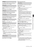
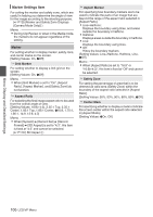
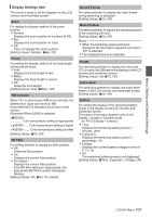
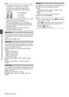
Menu Display and Detailed Settings SD Aspect For setting the style of displaying images with a 16:9 aspect ratio on a 4:3 aspect ratio screen. 0 Letter: Displays as a wide image with the top and bottom blackened. 0 Squeeze: Displays image that is squeezed horizontally. [Setting Values: Letter, RSqueeze] Memo : 0 When [Record Format] B [System] is set to "SD", and [Record Format] B [SD Aspect] is set to "4:3", "---" is displayed and selection is disabled. (A P115 [ System ] ) SD Set Up For selecting whether to add a setup signal to the video signal output from the [AV] output terminal. Setup signals are added when "7.5%" is selected. [Setting Values: 7.5%, 0.0%] (Default values: 7.5% (U model), fixed at "0.0%" (E model)) Memo : 0 Depending on the menu settings of the camera recorder and the condition of the cable connected to it, the setup signal setting may be fixed at "0.0%". "0.0%" is displayed in gray in this case. Audio Set Item CH1 INT For selecting either the built-in microphone or the [AUX] terminal as the CH1 audio input signal. This item is selectable if the [CH1] audio input signal selection switch is set to "INT" O, and a microphone is connected to the [AUX] terminal. 0 AUX L: Sets the [AUX] terminal as the CH1 audio input signal. 0 Int. Mic L: Sets the left channel (Lch) of the built-in microphone as the CH1 audio input signal. [Setting Values: RAUX L, Int. Mic L] Memo : 0 If the [AUX] terminal is not connected, this item is fixed at "Int. Mic L". 0 When the [CH1] audio input signal selection switch is set to a value other than "INT", "---" is displayed and selection is disabled. 0 If the handle unit is not connected, the state of the [CH1] audio input signal selection switch is equivalent to "INT". CH2 INT For selecting either the built-in microphone or the [AUX] terminal as the CH2 audio input signal. This item is selectable if the [CH2] audio input signal selection switch is set to "INT" O, and a microphone is connected to the [AUX] terminal. 0 AUX R: Sets the [AUX] terminal as the CH2 audio input signal. 0 Int. Mic R: Sets the right channel (Rch) of the built-in microphone as the CH2 audio input signal. [Setting Values: RAUX R, Int. Mic R] Memo : 0 If the [AUX] terminal is not connected, this item is fixed at "Int. Mic R". 0 When the [CH2] audio input signal selection switch is set to a value other than "INT", "---" is displayed and selection is disabled. 0 If the handle unit is not connected, the state of the [CH2] audio input signal selection switch is equivalent to "INT". Input1 Mic Ref./Input2 Mic Ref. O For setting the reference input level when the [INPUT1]/[INPUT2] selection switch is set to "MIC" or "MIC+48V". [Setting Values: -62dB, -56dB, R-50dB, -44dB, -38dB, -32dB] Memo : 0 This item is not displayed if the handle unit is not connected. Ref. Level For setting the recording reference level. (Applies to both [CH1/CH2].) [Setting Values: -12dB, -18dB, R-20dB] 110 A/V Set Menu
-
 1
1 -
2
-
3
-
4
-
5
-
6
-
7
-
8
-
9
-
10
-
11
-
12
-
13
-
14
-
15
-
16
-
17
-
18
-
19
-
20
-
21
-
22
-
23
-
24
-
25
-
26
-
27
-
28
-
29
-
30
-
31
-
32
-
33
-
34
-
35
-
36
-
37
-
38
-
39
-
40
-
41
-
42
-
43
-
44
-
45
-
46
-
47
-
48
-
49
-
50
-
51
-
52
-
53
-
54
-
55
-
56
-
57
-
58
-
59
-
60
-
61
-
62
-
63
-
64
-
65
-
66
-
67
-
68
-
69
-
70
-
71
-
72
-
73
-
74
-
75
-
76
-
77
-
78
-
79
-
80
-
81
-
82
-
83
-
84
-
85
-
86
-
87
-
88
-
89
-
90
-
91
-
92
-
93
-
94
-
95
-
96
-
97
-
98
-
99
-
100
-
101
-
102
-
103
-
104
-
 105
105 -
 106
106 -
 107
107 -
 108
108 -
 109
109 -
 110
110 -
 111
111 -
 112
112 -
 113
113 -
 114
114 -
 115
115 -
116
-
117
-
118
-
119
-
120
-
121
-
122
-
123
-
124
-
125
-
126
-
127
-
128
-
129
-
130
-
131
-
132
-
133
-
134
-
135
-
136
-
137
-
138
-
139
-
140
-
141
-
142
-
143
-
144
-
145
-
146
-
147
-
148
-
149
-
150
-
151
-
152
-
153
-
154
-
155
-
156
-
157
-
158
-
159
-
160
-
161
-
162
-
163
-
164
-
165
-
166
-
167
-
168
-
169
-
170
-
171
-
172
-
173
-
174
-
175
-
176
-
177
-
178
-
179
-
180
-
181
-
182
-
183
-
184
 |
 |
