JVC GY-HM620U Instruction Manual - Page 114
AGC Mode, XLR Manual Level, Int. Mic Separation, Test Tone, INPUT1/2 Wind Cut, Int. Mic Wind Cut
 |
View all JVC GY-HM620U manuals
Add to My Manuals
Save this manual to your list of manuals |
Page 114 highlights
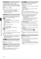
Menu Display and Detailed Settings AGC Mode For setting whether to link the limiter operation of [CH1] and [CH2]. Select "Link" to link or "Separate" to separate. [Setting Values: Link, RSeparate] Memo : 0 Enabled only when both the [AUX] input terminal and [INPUT1/INPUT2] input terminal are set to "LINE" or "MIC", and CH1/CH2 of the [CH1/CH2 AUTO/MANUAL] switch is set to "AUTO". XLR Manual Level For setting whether to link manual audio adjustment operation between [INPUT1] and [INPUT2] terminals. Select "Link" to link or "Separate" to separate. When this item is set to "Link", adjust the recording level using the [CH1] recording level adjustment knob. [Setting Values: Link, RSeparate] Memo : 0 Enabled only when both the [INPUT1/INPUT2] input terminals are set to "LINE" or "MIC", and both [CH1]/[CH2] of the [CH1/CH2 AUTO/ MANUAL] selection switches are set to "MANUAL". 0 When this item is set to "Link", [CH2] recording level adjustment knob is disabled. Int. Mic Separation For setting the enhancement level of the stereo effect of the built-in microphone. 0 1 to 4: Enhances the stereo effect. Increasing the value increases the stereo effect. 0 Effect off: Does not enhance the stereo effect. 0 Mono: Sets the built-in microphone to monaural. [Setting Values: 1 to 4, Effect off, Mono (R2)] Memo : 0 When any value from 1 to 4 is selected, the sound quality changes slightly due to the process of enhancing the stereo effect. This is normal. 0 This menu is enabled when the [CH1]/[CH2] selection switch is set to "INT". Test Tone For specifying whether to output the audio test signals (1 kHz) during color bar output. [Setting Values: On, ROff] INPUT1/2 Wind Cut For selecting whether to cut the low frequencies of the audio input signals (low-cut) when the [INPUT1/ INPUT2] switch is set to "MIC" or "MIC+48V". Set this item to reduce wind noise from the microphone. 0 Both: Enables low-cut on both the [INPUT1] and [INPUT2] terminals. 0 INPUT2: Enables low-cut on the audio of the [INPUT2] terminal only. 0 INPUT1: Enables low-cut on the audio of the [INPUT1] terminal only. 0 Off: Disables low-cut. [Setting Values: Both, INPUT2, INPUT1, ROff] Int. Mic Wind Cut For selecting whether to cut the low frequencies of the audio input signals (low-cut) from the built-in microphone. Set this item to "On" to reduce wind noise from the microphone. [Setting Values: On, ROff] Equalizer You can correct the characteristic and enhance the sound of the connected microphone using this equalizer setting. For setting the audio frequency from a 5-band equalizer. 0 Frequency: 100Hz, 330Hz, 1kHz, 3.3kHz, 10kHz 0 Variable level: ± 6dB (1dB step) Memo : 0 Audio will be recorded in the characteristic set in the equalizer. 0 Set all bands to "0dB" to bypass the equalizer. 0 When the equalizer level is set to the + side, the audio may be distorted. In this case, reduce the recording level in Manual mode. 0 If the values of multiple frequencies are changed, the specified levels and the actual levels may be different due to interference between the frequency bands. 0 This function is enabled only when both [INPUT1/2 Wind Cut] and [Int. Mic Wind Cut] are set to "Off". 114
-
 1
1 -
2
-
3
-
4
-
5
-
6
-
7
-
8
-
9
-
10
-
11
-
12
-
13
-
14
-
15
-
16
-
17
-
18
-
19
-
20
-
21
-
22
-
23
-
24
-
25
-
26
-
27
-
28
-
29
-
30
-
31
-
32
-
33
-
34
-
35
-
36
-
37
-
38
-
39
-
40
-
41
-
42
-
43
-
44
-
45
-
46
-
47
-
48
-
49
-
50
-
51
-
52
-
53
-
54
-
55
-
56
-
57
-
58
-
59
-
60
-
61
-
62
-
63
-
64
-
65
-
66
-
67
-
68
-
69
-
70
-
71
-
72
-
73
-
74
-
75
-
76
-
77
-
78
-
79
-
80
-
81
-
82
-
83
-
84
-
85
-
86
-
87
-
88
-
89
-
90
-
91
-
92
-
93
-
94
-
95
-
96
-
97
-
98
-
99
-
100
-
101
-
102
-
103
-
104
-
105
-
106
-
107
-
108
-
 109
109 -
 110
110 -
 111
111 -
 112
112 -
 113
113 -
 114
114 -
 115
115 -
 116
116 -
 117
117 -
 118
118 -
 119
119 -
120
-
121
-
122
-
123
-
124
-
125
-
126
-
127
-
128
-
129
-
130
-
131
-
132
-
133
-
134
-
135
-
136
-
137
-
138
-
139
-
140
-
141
-
142
-
143
-
144
-
145
-
146
-
147
-
148
-
149
-
150
-
151
-
152
-
153
-
154
-
155
-
156
-
157
-
158
-
159
-
160
-
161
-
162
-
163
-
164
-
165
-
166
-
167
-
168
-
169
-
170
-
171
-
172
-
173
-
174
-
175
-
176
-
177
-
178
-
179
-
180
-
181
-
182
-
183
-
184
-
185
-
186
-
187
-
188
-
189
-
190
-
191
-
192
 |
 |