Netgear GS748TS GS7xxTS User Manual - Page 133
MST Port Configuration
 |
UPC - 606449049480
View all Netgear GS748TS manuals
Add to My Manuals
Save this manual to your list of manuals |
Page 133 highlights
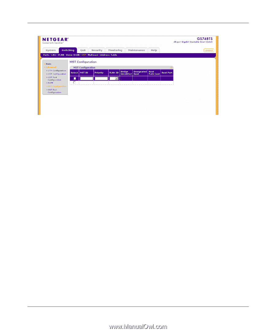
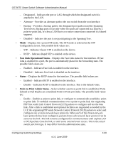
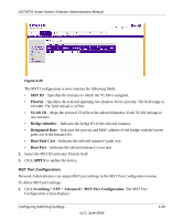
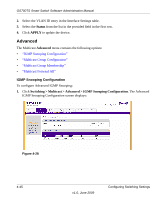
GS700TS Smart Switch Software Administration Manual Figure 4-25 The MST Configuration screen contains the following fields: • MST ID - Specifies the instance to which the VLAN is assigned. • Priority - Specifies the selected spanning tree instance device priority. The field range is 0-61440. The field default is 32768. • VLAN ID - Maps the selected VLANs to the selected instance. Each VLAN belongs to one instance. • Bridge Identifer - Indicates the bridge ID of the selected instance. • Designated Root - Indicates the priority and MAC address of the bridge with the lowest path cost to the instance ID. • Root Path Cost - Indicates the selected instance's path cost. • Root Port - Indicates the selected instance's root port. 2. Select the MST ID and enter Priority field 3. Click APPLY to update the device. MST Port Configuration Network Administrators can assign MST port settings in the MST Port Configuration screen. To define MST port settings: 1. Click Switching > STP > Advanced > MST Port Configuration. The MST Port Configuration screen displays: Configuring Switching Settings v1.0, June 2009 4-40
-
 1
1 -
2
-
3
-
4
-
5
-
6
-
7
-
8
-
9
-
10
-
11
-
12
-
13
-
14
-
15
-
16
-
17
-
18
-
19
-
20
-
21
-
22
-
23
-
24
-
25
-
26
-
27
-
28
-
29
-
30
-
31
-
32
-
33
-
34
-
35
-
36
-
37
-
38
-
39
-
40
-
41
-
42
-
43
-
44
-
45
-
46
-
47
-
48
-
49
-
50
-
51
-
52
-
53
-
54
-
55
-
56
-
57
-
58
-
59
-
60
-
61
-
62
-
63
-
64
-
65
-
66
-
67
-
68
-
69
-
70
-
71
-
72
-
73
-
74
-
75
-
76
-
77
-
78
-
79
-
80
-
81
-
82
-
83
-
84
-
85
-
86
-
87
-
88
-
89
-
90
-
91
-
92
-
93
-
94
-
95
-
96
-
97
-
98
-
99
-
100
-
101
-
102
-
103
-
104
-
105
-
106
-
107
-
108
-
109
-
110
-
111
-
112
-
113
-
114
-
115
-
116
-
117
-
118
-
119
-
120
-
121
-
122
-
123
-
124
-
125
-
126
-
127
-
 128
128 -
 129
129 -
 130
130 -
 131
131 -
 132
132 -
 133
133 -
 134
134 -
 135
135 -
 136
136 -
 137
137 -
 138
138 -
139
-
140
-
141
-
142
-
143
-
144
-
145
-
146
-
147
-
148
-
149
-
150
-
151
-
152
-
153
-
154
-
155
-
156
-
157
-
158
-
159
-
160
-
161
-
162
-
163
-
164
-
165
-
166
-
167
-
168
-
169
-
170
-
171
-
172
-
173
-
174
-
175
-
176
-
177
-
178
-
179
-
180
-
181
-
182
-
183
-
184
-
185
-
186
-
187
-
188
-
189
-
190
-
191
-
192
-
193
-
194
-
195
-
196
-
197
-
198
-
199
-
200
-
201
-
202
-
203
-
204
-
205
-
206
-
207
-
208
-
209
-
210
-
211
-
212
-
213
-
214
-
215
-
216
-
217
-
218
-
219
-
220
-
221
-
222
-
223
-
224
-
225
-
226
-
227
-
228
-
229
-
230
-
231
-
232
 |
 |