Netgear GS748TS GS7xxTS User Manual - Page 45
Stacking Ports, Stacking Members and Unit No., Stacking Ring Topology - hdmi
 |
UPC - 606449049480
View all Netgear GS748TS manuals
Add to My Manuals
Save this manual to your list of manuals |
Page 45 highlights
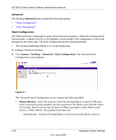
GS700TS Smart Switch Software Administration Manual connects stacking members from one to the next. This provides a single data path flow. The stacking members linked in the middle of the chain are connected to the stacking member on either side of them. The members at the end of the chain only have one connection. Stacking Ring Topology One of the benefits of the Ring topology is that it offers redundancy in case the connections between two units fail, including the case where a unit in the stack fails. If a failure occurs in the stacking topology, the stack reverts to the Chain stacking topology. In the Chain topology, devices operate in a chain formation. The system automatically switches to a Stacking Failover topology without any system downtime. An SNMP message is automatically generated, but no stack management action is required. However, the stacking link or stacking member must be repaired to return to the Ring topology. After the stacking issues are resolved, the device can be reconnected to the stack without interruption and the Ring topology is restored. Stacking Ports The mode type determines the Gigabit Ethernet ports that are configurable by the user. • In Standalone mode all Gigabit Ethernet ports are available. • In Stack mode two dedicated Gigabit Ethernet ports are used for stack connection. The factory default of the device is stack mode. Use the System Information screen to change the unit mode from Standalone to Stack mode. The ports used for stacking can be either the combo ports or the copper ports. By default, the copper ports are reserved for stacking. The Stack Management screen allows network managers to configure the combo ports as the stacking ports. Two full-duplex stacking link up/down ports are available via HDMI connectors and provide 10 Gps throughput stacking capacity. Stacking Members and Unit No. Stacking Unit Numbers are essential to the stacking configuration. Unit No. 1 and Unit No. 2 are reserved for Master enabled units. Unit Numbers 3 to 6 can be defined for stack members. When the Master unit boots or when inserting or removing a stack member, the Master unit initiates a stacking discovering process. If two members are discovered with the same Unit No., the stack continues to function. However, only the unit with the older join time joins the stack. A message is sent to the user, notifying that a unit failed to join the stack. Managing System Settings v1.0, June 2009 3-10
-
 1
1 -
2
-
3
-
4
-
5
-
6
-
7
-
8
-
9
-
10
-
11
-
12
-
13
-
14
-
15
-
16
-
17
-
18
-
19
-
20
-
21
-
22
-
23
-
24
-
25
-
26
-
27
-
28
-
29
-
30
-
31
-
32
-
33
-
34
-
35
-
36
-
37
-
38
-
39
-
 40
40 -
 41
41 -
 42
42 -
 43
43 -
 44
44 -
 45
45 -
 46
46 -
 47
47 -
 48
48 -
 49
49 -
 50
50 -
51
-
52
-
53
-
54
-
55
-
56
-
57
-
58
-
59
-
60
-
61
-
62
-
63
-
64
-
65
-
66
-
67
-
68
-
69
-
70
-
71
-
72
-
73
-
74
-
75
-
76
-
77
-
78
-
79
-
80
-
81
-
82
-
83
-
84
-
85
-
86
-
87
-
88
-
89
-
90
-
91
-
92
-
93
-
94
-
95
-
96
-
97
-
98
-
99
-
100
-
101
-
102
-
103
-
104
-
105
-
106
-
107
-
108
-
109
-
110
-
111
-
112
-
113
-
114
-
115
-
116
-
117
-
118
-
119
-
120
-
121
-
122
-
123
-
124
-
125
-
126
-
127
-
128
-
129
-
130
-
131
-
132
-
133
-
134
-
135
-
136
-
137
-
138
-
139
-
140
-
141
-
142
-
143
-
144
-
145
-
146
-
147
-
148
-
149
-
150
-
151
-
152
-
153
-
154
-
155
-
156
-
157
-
158
-
159
-
160
-
161
-
162
-
163
-
164
-
165
-
166
-
167
-
168
-
169
-
170
-
171
-
172
-
173
-
174
-
175
-
176
-
177
-
178
-
179
-
180
-
181
-
182
-
183
-
184
-
185
-
186
-
187
-
188
-
189
-
190
-
191
-
192
-
193
-
194
-
195
-
196
-
197
-
198
-
199
-
200
-
201
-
202
-
203
-
204
-
205
-
206
-
207
-
208
-
209
-
210
-
211
-
212
-
213
-
214
-
215
-
216
-
217
-
218
-
219
-
220
-
221
-
222
-
223
-
224
-
225
-
226
-
227
-
228
-
229
-
230
-
231
-
232
 |
 |