Brother International MFC 8500 Service Manual - Page 102
Clutch Levers, Cassette Guide L, and Solenoid, Remove screw b and take off the solenoid.
 |
UPC - 012502603832
View all Brother International MFC 8500 manuals
Add to My Manuals
Save this manual to your list of manuals |
Page 102 highlights
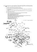
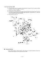
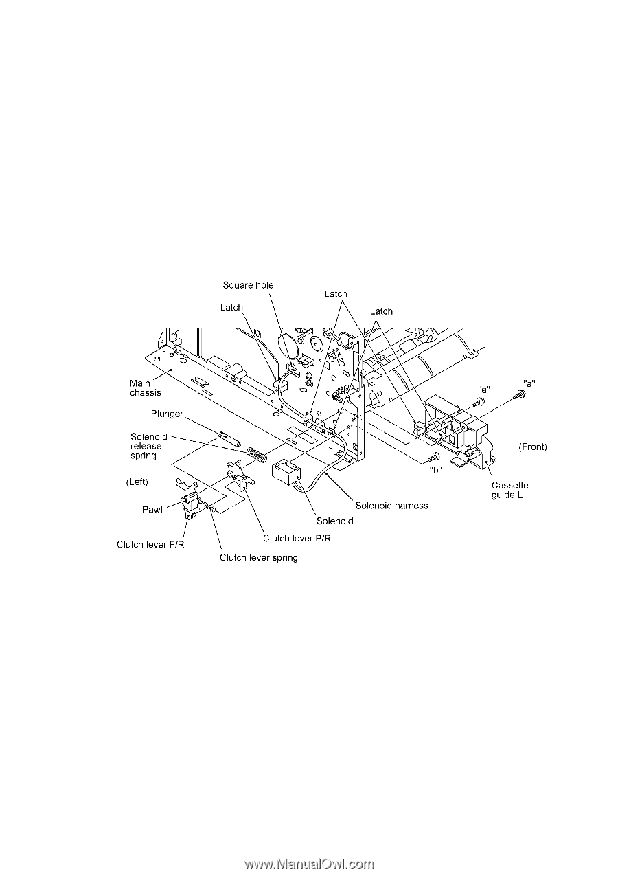
1.27 Clutch Levers, Cassette Guide L, and Solenoid (1) Turn the main chassis upside down. (2) Remove the two screws and take off the front underbar (which is shown on page IV-54). (3) Place the main chassis rightside up. (4) Remove the clutch lever F/R by pulling its pawl outwards. (5) Remove the clutch lever spring and clutch lever P/R. (6) Remove the plunger and solenoid release spring. (7) Remove two screws "a" and take off the cassette guide L. (8) Remove screw "b" and take off the solenoid. "a": Taptite, cup S M3x6 "b": Screw, bind M3x4 Reassembling Notes • Route the solenoid harness through three latches and pass it through the square hole provided in the left-hand plate of the main chassis. IV - 61
-
 1
1 -
2
-
3
-
4
-
5
-
6
-
7
-
8
-
9
-
10
-
11
-
12
-
13
-
14
-
15
-
16
-
17
-
18
-
19
-
20
-
21
-
22
-
23
-
24
-
25
-
26
-
27
-
28
-
29
-
30
-
31
-
32
-
33
-
34
-
35
-
36
-
37
-
38
-
39
-
40
-
41
-
42
-
43
-
44
-
45
-
46
-
47
-
48
-
49
-
50
-
51
-
52
-
53
-
54
-
55
-
56
-
57
-
58
-
59
-
60
-
61
-
62
-
63
-
64
-
65
-
66
-
67
-
68
-
69
-
70
-
71
-
72
-
73
-
74
-
75
-
76
-
77
-
78
-
79
-
80
-
81
-
82
-
83
-
84
-
85
-
86
-
87
-
88
-
89
-
90
-
91
-
92
-
93
-
94
-
95
-
96
-
 97
97 -
 98
98 -
 99
99 -
 100
100 -
 101
101 -
 102
102 -
 103
103 -
 104
104 -
 105
105 -
 106
106 -
 107
107 -
108
-
109
-
110
-
111
-
112
-
113
-
114
-
115
-
116
-
117
-
118
-
119
-
120
-
121
-
122
-
123
-
124
-
125
-
126
-
127
-
128
-
129
-
130
-
131
-
132
-
133
-
134
-
135
-
136
-
137
-
138
-
139
-
140
-
141
-
142
-
143
-
144
-
145
-
146
-
147
-
148
-
149
-
150
-
151
-
152
-
153
-
154
-
155
-
156
-
157
-
158
-
159
-
160
-
161
-
162
-
163
-
164
-
165
-
166
-
167
-
168
-
169
-
170
-
171
-
172
-
173
-
174
-
175
-
176
-
177
-
178
-
179
-
180
-
181
-
182
-
183
-
184
-
185
-
186
-
187
-
188
-
189
-
190
-
191
-
192
-
193
-
194
-
195
-
196
-
197
-
198
-
199
-
200
-
201
-
202
-
203
-
204
-
205
-
206
-
207
-
208
-
209
-
210
-
211
-
212
-
213
-
214
-
215
-
216
-
217
-
218
-
219
-
220
-
221
-
222
-
223
-
224
-
225
-
226
-
227
-
228
-
229
-
230
-
231
-
232
-
233
-
234
-
235
-
236
-
237
-
238
-
239
 |
 |
IV
- 61
1.27
Clutch Levers, Cassette Guide L, and Solenoid
(1)
Turn the main chassis upside down.
(2)
Remove the two screws and take off the front underbar (which is shown on page IV-54).
(3)
Place the main chassis rightside up.
(4)
Remove the clutch lever F/R by pulling its pawl outwards.
(5)
Remove the clutch lever spring and clutch lever P/R.
(6)
Remove the plunger and solenoid release spring.
(7)
Remove two screws "a" and take off the cassette guide L.
(8)
Remove screw "b" and take off the solenoid.
±
Reassembling Notes
•
Route the solenoid harness through three latches and pass it through the square hole provided
in the left-hand plate of the main chassis.
"a":
Taptite, cup S M3x6
"b":
Screw, bind M3x4