Brother International MFC 8500 Service Manual - Page 74
Do not touch the surface of the halogen lamp. If you have touched it, clean it, heater roller.
 |
UPC - 012502603832
View all Brother International MFC 8500 manuals
Add to My Manuals
Save this manual to your list of manuals |
Page 74 highlights
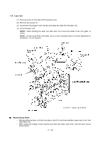
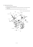
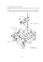
(6) Separate the lower FU frame from the upper one. Boss Hook Upper FU frame Boss Lower FU frame Hook (7) Remove the screw securing the lamp lock plate at the gear side of the upper FU frame. At the other side, loosen the screw. (8) Slightly lift up the right-hand end of the heater roller and pull out the halogen lamp from the heater roller. CAUTION: Do not touch the surface of the halogen lamp. If you have touched it, clean it thoroughly with alcohol. Screw, cup M3x6 (Loosen this.) Halogen lamp Colored end 115V: Yellow 230V: Purple Heater roller Heater roller Halogen lamp Screw Lamp lock plate Upper FU frame NOTE: When setting the halogen lamp into the heat-fixing unit, be careful with the insertion direction as shown above. IV - 33
-
 1
1 -
2
-
3
-
4
-
5
-
6
-
7
-
8
-
9
-
10
-
11
-
12
-
13
-
14
-
15
-
16
-
17
-
18
-
19
-
20
-
21
-
22
-
23
-
24
-
25
-
26
-
27
-
28
-
29
-
30
-
31
-
32
-
33
-
34
-
35
-
36
-
37
-
38
-
39
-
40
-
41
-
42
-
43
-
44
-
45
-
46
-
47
-
48
-
49
-
50
-
51
-
52
-
53
-
54
-
55
-
56
-
57
-
58
-
59
-
60
-
61
-
62
-
63
-
64
-
65
-
66
-
67
-
68
-
 69
69 -
 70
70 -
 71
71 -
 72
72 -
 73
73 -
 74
74 -
 75
75 -
 76
76 -
 77
77 -
 78
78 -
 79
79 -
80
-
81
-
82
-
83
-
84
-
85
-
86
-
87
-
88
-
89
-
90
-
91
-
92
-
93
-
94
-
95
-
96
-
97
-
98
-
99
-
100
-
101
-
102
-
103
-
104
-
105
-
106
-
107
-
108
-
109
-
110
-
111
-
112
-
113
-
114
-
115
-
116
-
117
-
118
-
119
-
120
-
121
-
122
-
123
-
124
-
125
-
126
-
127
-
128
-
129
-
130
-
131
-
132
-
133
-
134
-
135
-
136
-
137
-
138
-
139
-
140
-
141
-
142
-
143
-
144
-
145
-
146
-
147
-
148
-
149
-
150
-
151
-
152
-
153
-
154
-
155
-
156
-
157
-
158
-
159
-
160
-
161
-
162
-
163
-
164
-
165
-
166
-
167
-
168
-
169
-
170
-
171
-
172
-
173
-
174
-
175
-
176
-
177
-
178
-
179
-
180
-
181
-
182
-
183
-
184
-
185
-
186
-
187
-
188
-
189
-
190
-
191
-
192
-
193
-
194
-
195
-
196
-
197
-
198
-
199
-
200
-
201
-
202
-
203
-
204
-
205
-
206
-
207
-
208
-
209
-
210
-
211
-
212
-
213
-
214
-
215
-
216
-
217
-
218
-
219
-
220
-
221
-
222
-
223
-
224
-
225
-
226
-
227
-
228
-
229
-
230
-
231
-
232
-
233
-
234
-
235
-
236
-
237
-
238
-
239
 |
 |
IV
- 33
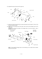
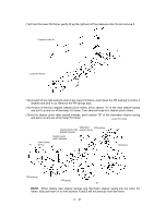
(6)
Separate the lower FU frame from the upper one.
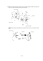
(7)
Remove the screw securing the lamp lock plate at the gear side of the upper FU frame. At the
other side, loosen the screw.
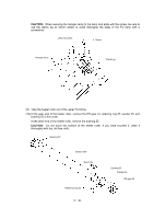
(8)
Slightly lift up the right-hand end of the heater roller and pull out the halogen lamp from the
heater roller.
CAUTION:
Do not touch the surface of the halogen lamp. If you have touched it, clean it
thoroughly with alcohol.
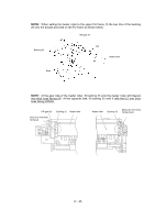
NOTE:
When setting the halogen lamp into the heat-fixing unit, be careful with the insertion
direction as shown above.
Upper FU frame
Boss
Hook
Lower FU frame
Boss
Hook
Halogen lamp
Heater roller
Screw, cup M3x6
(Loosen this.)
Heater roller
Halogen lamp
Lamp lock plate
Screw
Colored end
115V: Yellow
230V: Purple
Upper FU frame