Brother International MFC 8500 Service Manual - Page 75
bushing 25 in this order., At the other end of the heater roller, remove the bushing 25.
 |
UPC - 012502603832
View all Brother International MFC 8500 manuals
Add to My Manuals
Save this manual to your list of manuals |
Page 75 highlights
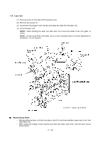
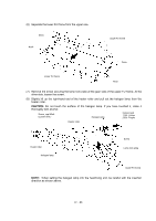
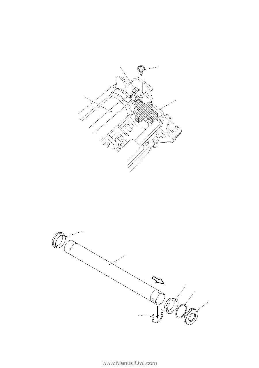
CAUTION: When securing the halogen lamp to the lamp lock plate with the screw, be sure to use the plastic jig as shown below to avoid damaging the edge of the FU lamp with a screwdriver. Lamp lock plate Screw Halogen lamp Plastic jig (9) Take the heater roller out of the upper FU frame. (10) At the gear side of the heater roller, remove the HR gear 34, retaining ring 25, washer 25, and bushing 25 in this order. At the other end of the heater roller, remove the bushing 25. CAUTION: Do not touch the surface of the heater roller. If you have touched it, clean it thoroughly with dry, lint-free cloth. Bushing 25 Heater roller Gear side Retaining ring 25 IV - 34 Bushing 25 Washer 25 HR gear 34
-
 1
1 -
2
-
3
-
4
-
5
-
6
-
7
-
8
-
9
-
10
-
11
-
12
-
13
-
14
-
15
-
16
-
17
-
18
-
19
-
20
-
21
-
22
-
23
-
24
-
25
-
26
-
27
-
28
-
29
-
30
-
31
-
32
-
33
-
34
-
35
-
36
-
37
-
38
-
39
-
40
-
41
-
42
-
43
-
44
-
45
-
46
-
47
-
48
-
49
-
50
-
51
-
52
-
53
-
54
-
55
-
56
-
57
-
58
-
59
-
60
-
61
-
62
-
63
-
64
-
65
-
66
-
67
-
68
-
69
-
 70
70 -
 71
71 -
 72
72 -
 73
73 -
 74
74 -
 75
75 -
 76
76 -
 77
77 -
 78
78 -
 79
79 -
 80
80 -
81
-
82
-
83
-
84
-
85
-
86
-
87
-
88
-
89
-
90
-
91
-
92
-
93
-
94
-
95
-
96
-
97
-
98
-
99
-
100
-
101
-
102
-
103
-
104
-
105
-
106
-
107
-
108
-
109
-
110
-
111
-
112
-
113
-
114
-
115
-
116
-
117
-
118
-
119
-
120
-
121
-
122
-
123
-
124
-
125
-
126
-
127
-
128
-
129
-
130
-
131
-
132
-
133
-
134
-
135
-
136
-
137
-
138
-
139
-
140
-
141
-
142
-
143
-
144
-
145
-
146
-
147
-
148
-
149
-
150
-
151
-
152
-
153
-
154
-
155
-
156
-
157
-
158
-
159
-
160
-
161
-
162
-
163
-
164
-
165
-
166
-
167
-
168
-
169
-
170
-
171
-
172
-
173
-
174
-
175
-
176
-
177
-
178
-
179
-
180
-
181
-
182
-
183
-
184
-
185
-
186
-
187
-
188
-
189
-
190
-
191
-
192
-
193
-
194
-
195
-
196
-
197
-
198
-
199
-
200
-
201
-
202
-
203
-
204
-
205
-
206
-
207
-
208
-
209
-
210
-
211
-
212
-
213
-
214
-
215
-
216
-
217
-
218
-
219
-
220
-
221
-
222
-
223
-
224
-
225
-
226
-
227
-
228
-
229
-
230
-
231
-
232
-
233
-
234
-
235
-
236
-
237
-
238
-
239
 |
 |
IV
- 34
CAUTION:
When securing the halogen lamp to the lamp lock plate with the screw, be sure to
use the plastic jig as shown below to avoid damaging the edge of the FU lamp with a
screwdriver.
(9)
Take the heater roller out of the upper FU frame.
(10) At the gear side of the heater roller, remove the HR gear 34, retaining ring 25, washer 25, and
bushing 25 in this order.
At the other end of the heater roller, remove the bushing 25.
CAUTION:
Do not touch the surface of the heater roller. If you have touched it, clean it
thoroughly with dry, lint-free cloth.
Lamp lock plate
Screw
Plastic jig
Halogen lamp
Bushing 25
Heater roller
Bushing 25
Washer 25
HR gear 34
Retaining ring 25
Gear side