Brother International MFC 8500 Service Manual - Page 63
Disconnect the hook switch harness from the hook switch PCB.
 |
UPC - 012502603832
View all Brother International MFC 8500 manuals
Add to My Manuals
Save this manual to your list of manuals |
Page 63 highlights
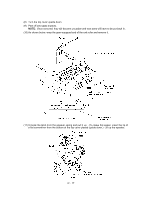
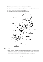
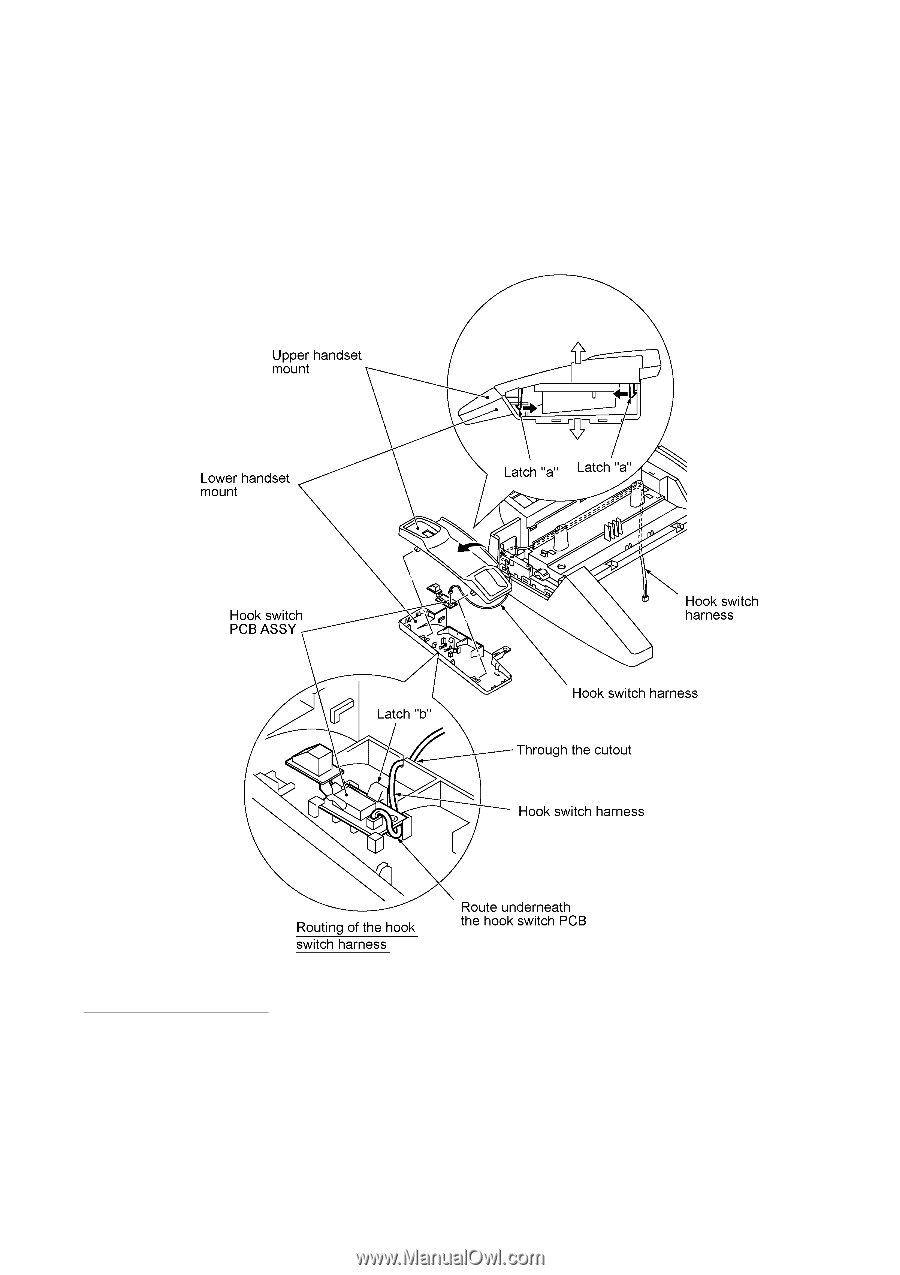
The following steps should apply to those models equipped with a handset: (3) Disassemble the handset mount by unhooking two latches "a" of the upper handset mount with a flat screwdriver. (4) Remove the hook switch PCB ASSY by unhooking latch "b." (5) Disconnect the hook switch harness from the hook switch PCB. n Reassembling Notes • When assembling the upper and lower handset mounts, route the hook switch harness underneath the hook switch PCB and through the cutout as shown above. Take care not to pinch the harness between the upper and lower mounts. • Make sure that the hook switch harness is routed along the guides on the top cover. IV - 22
-
 1
1 -
2
-
3
-
4
-
5
-
6
-
7
-
8
-
9
-
10
-
11
-
12
-
13
-
14
-
15
-
16
-
17
-
18
-
19
-
20
-
21
-
22
-
23
-
24
-
25
-
26
-
27
-
28
-
29
-
30
-
31
-
32
-
33
-
34
-
35
-
36
-
37
-
38
-
39
-
40
-
41
-
42
-
43
-
44
-
45
-
46
-
47
-
48
-
49
-
50
-
51
-
52
-
53
-
54
-
55
-
56
-
57
-
 58
58 -
 59
59 -
 60
60 -
 61
61 -
 62
62 -
 63
63 -
 64
64 -
 65
65 -
 66
66 -
 67
67 -
 68
68 -
69
-
70
-
71
-
72
-
73
-
74
-
75
-
76
-
77
-
78
-
79
-
80
-
81
-
82
-
83
-
84
-
85
-
86
-
87
-
88
-
89
-
90
-
91
-
92
-
93
-
94
-
95
-
96
-
97
-
98
-
99
-
100
-
101
-
102
-
103
-
104
-
105
-
106
-
107
-
108
-
109
-
110
-
111
-
112
-
113
-
114
-
115
-
116
-
117
-
118
-
119
-
120
-
121
-
122
-
123
-
124
-
125
-
126
-
127
-
128
-
129
-
130
-
131
-
132
-
133
-
134
-
135
-
136
-
137
-
138
-
139
-
140
-
141
-
142
-
143
-
144
-
145
-
146
-
147
-
148
-
149
-
150
-
151
-
152
-
153
-
154
-
155
-
156
-
157
-
158
-
159
-
160
-
161
-
162
-
163
-
164
-
165
-
166
-
167
-
168
-
169
-
170
-
171
-
172
-
173
-
174
-
175
-
176
-
177
-
178
-
179
-
180
-
181
-
182
-
183
-
184
-
185
-
186
-
187
-
188
-
189
-
190
-
191
-
192
-
193
-
194
-
195
-
196
-
197
-
198
-
199
-
200
-
201
-
202
-
203
-
204
-
205
-
206
-
207
-
208
-
209
-
210
-
211
-
212
-
213
-
214
-
215
-
216
-
217
-
218
-
219
-
220
-
221
-
222
-
223
-
224
-
225
-
226
-
227
-
228
-
229
-
230
-
231
-
232
-
233
-
234
-
235
-
236
-
237
-
238
-
239
 |
 |
IV
- 22
The following steps should apply to those models equipped with a handset:
(3)
Disassemble the handset mount by unhooking two latches "a" of the upper handset mount with
a flat screwdriver.
(4)
Remove the hook switch PCB ASSY by unhooking latch "b."
(5)
Disconnect the hook switch harness from the hook switch PCB.
n
Reassembling Notes
•
When assembling the upper and lower handset mounts, route the hook switch harness
underneath the hook switch PCB and through the cutout as shown above.
Take care not to
pinch the harness between the upper and lower mounts.
•
Make sure that the hook switch harness is routed along the guides on the top cover.