Brother International MFC 8500 Service Manual - Page 51
CIS Unit, The CIS springs also come off.
 |
UPC - 012502603832
View all Brother International MFC 8500 manuals
Add to My Manuals
Save this manual to your list of manuals |
Page 51 highlights
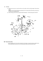
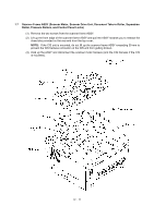
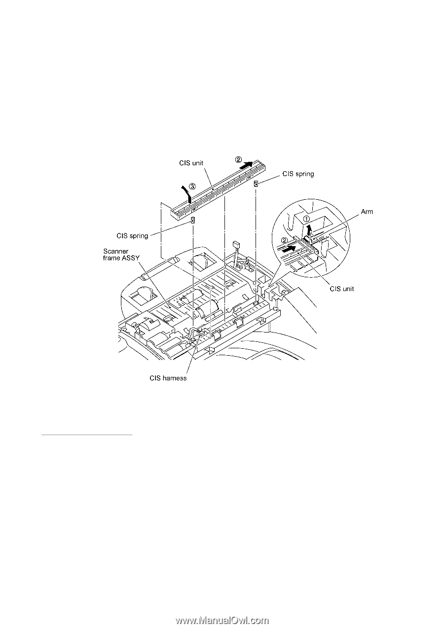
1.6 CIS Unit (1) Lightly pull up the arm, move the CIS unit to the right, and lift up the left edge of the CIS unit gently. NOTE: Do not lift up the left edge exceeding 30 mm to prevent the CIS harness connector on the CIS unit from getting broken. (2) While holding up the CIS unit, disconnect the CIS harness. The CIS springs also come off. n Reassembling Notes • When reinstalling the CIS unit, first connect the CIS harness, insert the right end under the arm of the scanner frame, put the CIS unit into the scanner frame, and then move it to left. IV - 10
-
 1
1 -
2
-
3
-
4
-
5
-
6
-
7
-
8
-
9
-
10
-
11
-
12
-
13
-
14
-
15
-
16
-
17
-
18
-
19
-
20
-
21
-
22
-
23
-
24
-
25
-
26
-
27
-
28
-
29
-
30
-
31
-
32
-
33
-
34
-
35
-
36
-
37
-
38
-
39
-
40
-
41
-
42
-
43
-
44
-
45
-
 46
46 -
 47
47 -
 48
48 -
 49
49 -
 50
50 -
 51
51 -
 52
52 -
 53
53 -
 54
54 -
 55
55 -
 56
56 -
57
-
58
-
59
-
60
-
61
-
62
-
63
-
64
-
65
-
66
-
67
-
68
-
69
-
70
-
71
-
72
-
73
-
74
-
75
-
76
-
77
-
78
-
79
-
80
-
81
-
82
-
83
-
84
-
85
-
86
-
87
-
88
-
89
-
90
-
91
-
92
-
93
-
94
-
95
-
96
-
97
-
98
-
99
-
100
-
101
-
102
-
103
-
104
-
105
-
106
-
107
-
108
-
109
-
110
-
111
-
112
-
113
-
114
-
115
-
116
-
117
-
118
-
119
-
120
-
121
-
122
-
123
-
124
-
125
-
126
-
127
-
128
-
129
-
130
-
131
-
132
-
133
-
134
-
135
-
136
-
137
-
138
-
139
-
140
-
141
-
142
-
143
-
144
-
145
-
146
-
147
-
148
-
149
-
150
-
151
-
152
-
153
-
154
-
155
-
156
-
157
-
158
-
159
-
160
-
161
-
162
-
163
-
164
-
165
-
166
-
167
-
168
-
169
-
170
-
171
-
172
-
173
-
174
-
175
-
176
-
177
-
178
-
179
-
180
-
181
-
182
-
183
-
184
-
185
-
186
-
187
-
188
-
189
-
190
-
191
-
192
-
193
-
194
-
195
-
196
-
197
-
198
-
199
-
200
-
201
-
202
-
203
-
204
-
205
-
206
-
207
-
208
-
209
-
210
-
211
-
212
-
213
-
214
-
215
-
216
-
217
-
218
-
219
-
220
-
221
-
222
-
223
-
224
-
225
-
226
-
227
-
228
-
229
-
230
-
231
-
232
-
233
-
234
-
235
-
236
-
237
-
238
-
239
 |
 |
IV
- 10
1.6
CIS Unit
(1)
Lightly pull up the arm, move the CIS unit to the right, and lift up the left edge of the CIS unit
gently.
NOTE:
Do not lift up the left edge exceeding 30 mm to prevent the CIS harness connector on
the CIS unit from getting broken.
(2)
While holding up the CIS unit, disconnect the CIS harness.
The CIS springs also come off.
n
Reassembling Notes
•
When reinstalling the CIS unit, first connect the CIS harness, insert the right end under the arm
of the scanner frame, put the CIS unit into the scanner frame, and then move it to left.